
By Dan Stern, photos & layout by D. Dutra
Slant Six Exhaust Manifold
Installation
By Dan Stern, photos & layout by D. Dutra
We will review the different exhaust manifolds available for the SL6 and discuss manifold preparation and installation.
All SL6 exhaust manifolds are basically the same and will interchange with all SL6 engines from 1960-86. There were some minor changes made to the exhaust manifolds over the years which added more reinforcement ribs and changed the choke stove pocket design. The first SL6 exhaust manifolds had no external ribbing and as a result, these crack and break easily. From these first manifold castings, this long cast iron exhaust manifold would prove to be a challenge to keep in one piece. As a result, the engineers added reinforcement ribs in an attempt to prevent cracking. Two external ribs were added in 1963 to stiffen the body of the manifold. 1970 added another bottom rib and ribs running up each runner "leg" . along with a revised (round) heat riser valve counterweight. By 1980 a thick section was added to the heat riser area's rear wall and this "boss" was drilled and tapped for an O2 sensor.
 The
important thing to remember is that this big, long exhaust manifold
is designed to "slide" across the gasket surface and move around as
it heats & cools. A stamped steel gasket is the best for allowing
movement but is also the hardest to seal. The thick material gaskets
are the opposite, easier to seal but they don't allow much manifold
movement, which can lead to a cracked manifold. The manifold
hardware is an important part of the installation. The special
washers allow the manifold some movement while holding it down for
sealing. The correct hardware must be used in the proper locations.
The two acorn nuts go on the two top, outer end studs, with the coned
shaped part of the nut fitting into the
The
important thing to remember is that this big, long exhaust manifold
is designed to "slide" across the gasket surface and move around as
it heats & cools. A stamped steel gasket is the best for allowing
movement but is also the hardest to seal. The thick material gaskets
are the opposite, easier to seal but they don't allow much manifold
movement, which can lead to a cracked manifold. The manifold
hardware is an important part of the installation. The special
washers allow the manifold some movement while holding it down for
sealing. The correct hardware must be used in the proper locations.
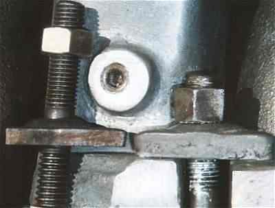
The two acorn nuts go on the two top, outer end studs, with the coned
shaped part of the nut fitting into the ![]() dished,
conical part of the round brass washers. The center three studs get
cup-shaped round cast iron washers, cupped faces towards the head.
Everything else gets triangular butterfly washers. (Link
to more manifold installation instructions.) Note
dished,
conical part of the round brass washers. The center three studs get
cup-shaped round cast iron washers, cupped faces towards the head.
Everything else gets triangular butterfly washers. (Link
to more manifold installation instructions.) Note  that
"later" SL6 engines came with only one round conical washer in the
top center position. All the other were triangular type. This
combination is also acceptable but installation of the lower, inner
triangle washers can be a challenge, especially the one under the
choke stove mounting pocket. A little grinding of the parting line in
this location really helps to get socket access to that nut. Use a
1/4" socket set for easiest access. All the tab surfaces where the
washers contact the manifold must be smooth and allow clearance on
all sides. You may have to grind the sharp corners off the edges of
the tab cutouts to ensure this. I use some anti-seize compound on the
resurfaced flats to help the manifold "float" under the washers.
that
"later" SL6 engines came with only one round conical washer in the
top center position. All the other were triangular type. This
combination is also acceptable but installation of the lower, inner
triangle washers can be a challenge, especially the one under the
choke stove mounting pocket. A little grinding of the parting line in
this location really helps to get socket access to that nut. Use a
1/4" socket set for easiest access. All the tab surfaces where the
washers contact the manifold must be smooth and allow clearance on
all sides. You may have to grind the sharp corners off the edges of
the tab cutouts to ensure this. I use some anti-seize compound on the
resurfaced flats to help the manifold "float" under the washers.
 Choke
Spring (stove) Mounting
Choke
Spring (stove) Mounting
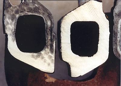
The choke stove mounting pocket came in three permutations:
- A cast-in pocket with a small
section of the rear casting wall missing.
- A pocket area
open to the exhaust port and the use of a stamped steel "cup and
gasket" to seal the hole.
- A cast-in pocket
with the entire rear wall removed. This allows room for the Super Six
2 bbl choke stove.
 There
are different choke stoves for these
different pockets so be sure to use the correct unit. The spring
tension can be adjusted on many of these by using a 3/8
wrench on the spring retaining nut and rotating the spring's
anchor point.
There
are different choke stoves for these
different pockets so be sure to use the correct unit. The spring
tension can be adjusted on many of these by using a 3/8
wrench on the spring retaining nut and rotating the spring's
anchor point.
Gaskets
The factory used a stamped steel gasket between the manifold set
and head. This worked well on the freshly machined surfaces of new
engines. For used / worn surfaces, use a composition gasket. I like
NAPA's #MS-16030 better than Fel-Pro's gasket for this  application.
There is also the very thick Mr. Gasket #320 as well as special
"engineered
application.
There is also the very thick Mr. Gasket #320 as well as special
"engineered material" gaskets from Cox Performance and Clifford. These can be
useful if you suspect leakage from from headers because of flange
warping. The original type embossed
metal shim (thin) gaskets don't seal well on used surfaces that
are pitted or not completely flat. Forget about the "Fig Newton"
gasket, (paper on the intake ports, metal on the exhaust) because
these take extra intake / exhaust manifold realignment work to get
sealed. This "two-in-one" gasket was sold by McCord and (sometimes)
Chrysler's aftermarket parts department. There are a number of
different gasket types used for the
inter-manifold and header pipe flange connection so look at different
manufacture's sets if you have a need for a special type.
material" gaskets from Cox Performance and Clifford. These can be
useful if you suspect leakage from from headers because of flange
warping. The original type embossed
metal shim (thin) gaskets don't seal well on used surfaces that
are pitted or not completely flat. Forget about the "Fig Newton"
gasket, (paper on the intake ports, metal on the exhaust) because
these take extra intake / exhaust manifold realignment work to get
sealed. This "two-in-one" gasket was sold by McCord and (sometimes)
Chrysler's aftermarket parts department. There are a number of
different gasket types used for the
inter-manifold and header pipe flange connection so look at different
manufacture's sets if you have a need for a special type.
Gasket Goop
 Sometimes
sealer is helpful, other times it is not. If your manifolds and/or
the head surface is warped, it can mean the difference between a
successful seal or the "rework" of a time-consuming task. The
cardinal rule of gasket sealer is best remembered by thinking back to
the cardinal rule of grammar-school arts and crafts: "DON'T BE A
PASTE WASTER!" In other words, use any sealer sparingly. You do not
need a lot to do the job. There is an open debate on where to use
what type of sealer. In general, most agree that you can use a good
high temp. sealer on the gasket face contacting the head, as well as
sealer on both sides of the "heat box" inter-manifold gasket used
between the intake and exhaust manifolds. As for using sealer on the
gasket surface contacting the manifold ports, I coat that side, Dutra
puts a little around the intake ports only and others use no sealer
on that side. Many racers use no sealer at all. Do what works best
for your manifold setup.
Sometimes
sealer is helpful, other times it is not. If your manifolds and/or
the head surface is warped, it can mean the difference between a
successful seal or the "rework" of a time-consuming task. The
cardinal rule of gasket sealer is best remembered by thinking back to
the cardinal rule of grammar-school arts and crafts: "DON'T BE A
PASTE WASTER!" In other words, use any sealer sparingly. You do not
need a lot to do the job. There is an open debate on where to use
what type of sealer. In general, most agree that you can use a good
high temp. sealer on the gasket face contacting the head, as well as
sealer on both sides of the "heat box" inter-manifold gasket used
between the intake and exhaust manifolds. As for using sealer on the
gasket surface contacting the manifold ports, I coat that side, Dutra
puts a little around the intake ports only and others use no sealer
on that side. Many racers use no sealer at all. Do what works best
for your manifold setup.
For a long time, high temp. RTV Silicone was the only option for exhaust manifolds. Now there is something better for this application. It is a blue polymeric gel called "Hylomar". It is much, much easier to work with, more flexible, more removable, and generally much better suited to this application. I have had excellent success with the variety in the squeeze tube labeled "Hylomar HPF/High Performance Formula". Make a thin ring, (you don't need much) around each port on one side of the gasket. It doesn't need to be used so thickly that it gooshes out all over the place but be sure there is an unbroken ring around each port opening. Put the coated gasket on the clean cylinder head surface and press it into place with your fingertips. Now it's easier to put beads of Hylomar on the manifold side instead of trying to figure out a way to spread Hylomar on both sides of the gasket before installing it.
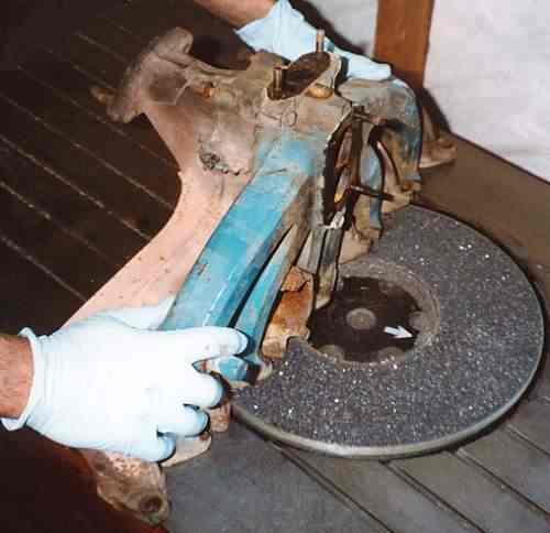
Manifold Preparation
The first step before you disassemble the manifold set is to check the intake to exhaust manifold port alignment. Run a straight edge along the bottom of the port openings or use a new gasket to see if the exhaust manifold is warped. Pay close attention to the end exhaust manifold ports. It is common to see these ports slightly higher than the others in the row. If the end ports are higher by more than .100 it will be difficult to get the end ports to seal. (Very little gasket contact area remains.) It is possible to do some minor location adjusting by "offset" grinding / filing on the heat box contact surfaces between the two manifolds.
After you've disassembled the intake from the exhaust, inspect for
cracks and deburr the manifolds. The port openings are the obvious
places to grind but also do some work around the cutouts where the
triangular spanner washers seat. Another good place to grind is
under the choke stove pocket so
you have a little more room to fit in your socket for easy assembly.
I also smooth out any ragged casting parting lines or sharp edges
just so I don't nick myself on these while doing the assembly work.
 Next,
clean the heat pocket area of the intake. This is the area on the
underside of the intake manifold where it connects to the exhaust
manifold. Use a screwdriver to scrape away all the carbon buildup in
the manifold's heat pocket "hot spot" area. Really scrape hard in all
directions to chip away as much of the stuff as possible. A spray can
of Berryman B12 ChemTool carburetor cleaner helps here. If you wish
to be fastidious, have the manifold media blasted (bead, sand, brake
lathe shavings, whatever your local blaster uses). Removing all the
carbon from this heat transfer area helps heat transfer to the
intake. Note that later intake manifolds have a larger carb. heat
pocket and have a larger hole to accept a 3/8 - 16 unc stud in the
inner position. Earlier intake manifolds will need to have this hole
drilled out if they are to be used with later exhaust manifolds using
the larger stud. Wash out the reworked manifolds completely after
your are done and repaint. This is especially important with intake
manifolds that have been media blasted.
Next,
clean the heat pocket area of the intake. This is the area on the
underside of the intake manifold where it connects to the exhaust
manifold. Use a screwdriver to scrape away all the carbon buildup in
the manifold's heat pocket "hot spot" area. Really scrape hard in all
directions to chip away as much of the stuff as possible. A spray can
of Berryman B12 ChemTool carburetor cleaner helps here. If you wish
to be fastidious, have the manifold media blasted (bead, sand, brake
lathe shavings, whatever your local blaster uses). Removing all the
carbon from this heat transfer area helps heat transfer to the
intake. Note that later intake manifolds have a larger carb. heat
pocket and have a larger hole to accept a 3/8 - 16 unc stud in the
inner position. Earlier intake manifolds will need to have this hole
drilled out if they are to be used with later exhaust manifolds using
the larger stud. Wash out the reworked manifolds completely after
your are done and repaint. This is especially important with intake
manifolds that have been media blasted.
Get a can of genuine Chrysler MoPar Manifold Heat Control Valve solvent, available at any Chrysler Corp. dealer, to lube the heat riser valve bushing. This is a must, nothing else works as well. Spray this stuff liberally on inner and outer ends of both heat control valve bushings and work the valve back and forth, flushing / lubing with the heat control valve spray. Do this until the flap operates smoothly and freely. If it is stuck fast, remove the counterweight (the early flat type counterweight comes off fast), flood the bushings with the solvent spray and whack the ENDS of the shaft with a good hammer. Keep spraying and whacking the shaft back and fourth until it frees up. A little heat can help free up a really stuck one.
Next, you'll want to carefully prepare the surfaces for the new metal inter-manifold gasket. The current stamped steel replacement gaskets are poorly designed and tough to persuade to make a good seal so clean and file flat the contact areas. The old, long-obsolete "problem solver" gasket (a thicker metal-asbestos-metal sandwich material gasket) was much better at sealing a worn and pitted surface. My experience has taught me that unless you have reground these surfaces or have a brand new intake and a brand new exhaust manifold, this all-metal gasket simply will not seal on a worn surface. This is the place to use High Temp. RTV Silicone. I use copper high-heat RTV from the parts store or Chrysler Mopar High-Temp RTV to help ensure a seal.
 Before
we get to the actual application of goop to this gasket, you will
need to modify the stamped steel gasket slightly if you plan to use
it with a '70 or older exhaust manifold. Most of these gaskets have a
"bridge" part that runs across the center opening, from side to side.
This was intended to help direct the flow of exhaust through the hot
spot pockets in later manifolds, but this section of the gasket
interferes with the top of the '70 and earlier manifold heat control
valve "flapper", which sits higher in the exhaust manifold. The later
valves are mounted lower in the manifold and don't hit the gasket. To
make the modification, use a cutoff wheel in a Dremel tool or sharp
shears (fast) or a file or saw (slow) to cut back the straight
(non-curved) end of the bridge. Backcutting this bridge by about 1/8"
will solve the interference problem, or if you're running a '72 or
earlier intake, you can remove the bridge entirely. The valve catches
on the corners of the bridge where it meets the side rails of the
gasket. All of this will make sense once you see it, but note that
the interference won't happen until everything is assembled and
torqued, so if you have the early style heat control valve, DO THE
MODIFICATION, otherwise your heat control valve may not work right or
will get jammed in the closed position on the early style
manifolds.
Before
we get to the actual application of goop to this gasket, you will
need to modify the stamped steel gasket slightly if you plan to use
it with a '70 or older exhaust manifold. Most of these gaskets have a
"bridge" part that runs across the center opening, from side to side.
This was intended to help direct the flow of exhaust through the hot
spot pockets in later manifolds, but this section of the gasket
interferes with the top of the '70 and earlier manifold heat control
valve "flapper", which sits higher in the exhaust manifold. The later
valves are mounted lower in the manifold and don't hit the gasket. To
make the modification, use a cutoff wheel in a Dremel tool or sharp
shears (fast) or a file or saw (slow) to cut back the straight
(non-curved) end of the bridge. Backcutting this bridge by about 1/8"
will solve the interference problem, or if you're running a '72 or
earlier intake, you can remove the bridge entirely. The valve catches
on the corners of the bridge where it meets the side rails of the
gasket. All of this will make sense once you see it, but note that
the interference won't happen until everything is assembled and
torqued, so if you have the early style heat control valve, DO THE
MODIFICATION, otherwise your heat control valve may not work right or
will get jammed in the closed position on the early style
manifolds.
 To
prep the inter-manifold gasket, brush/blow off all the chips from the
bridge modification and then goop a medium-heavy layer of high heat
RTV silicone gasket material on both sides of the gasket, all the way
around its rectangular perimeter. Let the RTV "skin-over" for half an
hour or so. To install the manifold set, carefully place the
"gooped-and-skinned" inter-manifold gasket right-way-up between the
two manifolds, then just snug the three intake-to-exhaust bolts with
your fingers. (Use new, grade 8 bolts, coated with anti-seize, if you
ever want to take them out again without breaking them.) Then install
the pair of manifolds onto the cylinder head on which you've placed
the prepared 12-port gasket.
To
prep the inter-manifold gasket, brush/blow off all the chips from the
bridge modification and then goop a medium-heavy layer of high heat
RTV silicone gasket material on both sides of the gasket, all the way
around its rectangular perimeter. Let the RTV "skin-over" for half an
hour or so. To install the manifold set, carefully place the
"gooped-and-skinned" inter-manifold gasket right-way-up between the
two manifolds, then just snug the three intake-to-exhaust bolts with
your fingers. (Use new, grade 8 bolts, coated with anti-seize, if you
ever want to take them out again without breaking them.) Then install
the pair of manifolds onto the cylinder head on which you've placed
the prepared 12-port gasket.
 Install
all the washers and nuts. I like to use Dorman's brass nuts on the
studs because they don't seize and they look nice. A brush coat of
'Led Plate' (Briggs and Stratton 93963) or another good metallic
anti-seize compound on the stud threads and on the three bolts is a
wise move.
Install
all the washers and nuts. I like to use Dorman's brass nuts on the
studs because they don't seize and they look nice. A brush coat of
'Led Plate' (Briggs and Stratton 93963) or another good metallic
anti-seize compound on the stud threads and on the three bolts is a
wise move.
As for putting the bottom triangular washers onto the studs, it's
easier if you put one washer on the shaft of a phillips head
screwdriver or rod, then touch the screwdriver to the stud, then use
another driver to slide the washer onto the stud. Another technique
is to loop a piece of sewing thread or fishing line through the
washer eye, then lower the washer down between manifold runners,
guiding the washer onto the stud with a long screwdriver or
probe.
Tighten the manifold-to-head nuts. Start at the center and work
outward to snug, then go back and torque the three intake-to-exhaust
bolts to 22 foot pounds. Now go back and torque the head fasteners to
10-12 foot pounds of torque, again from the center outward.
--------------------------
A couple of additional comments on getting the factory intake & exhaust manifolds assembled and sealed-up properly:
Check any used manifold for warpage. Use the gasket as your
"inspection tool". If the end exhaust ports are more then 1/8" higher
than the intake port next to it, best find another
manifold.
Always do a "dry run" fit check. Assemble the intake manifold to exhaust manifold, with no gasket and the center 3 heat riser bolts making "light contact" but not torqued. Place the assembly directly on the head surface, no gasket, and install the fasteners. Look for warpage by using a .010 feeler gauge along the gasket surfaces and mark any places where the gauge slips in. Check the exhaust pipe connection point to be sure the pipe flange meets the manifold surface square and flat. This will give even "crush" on the gasket for a trouble free seal. Inspect around each washer and stud. Do some grinding to remove casting flash or make additional clearance if you see any contact.
Remember, this big-long exhaust manifold is designed to "slide" across the gasket and move around as it heats & cools. If you pin it down by over-tightening or because it butts up on something, the manifold will flex, warp, crack, etc. Be sure the exhaust manifold does not contact a stud or that the washers do not rotate and jam up in the machined tab notch(s) as you tighten them. Use the correct brass washers on the top/end studs. The only thing that should contact the exhaust manifold are the faces of the washers, not their sides, not the studs, not the intake(except at the center heat riser pad). Grind away any interference. Do not "force on" the assembly or it will eventually crack the exhaust manifold, a stud or both.
To align the two manifolds, assemble the manifolds with the 3 heat riser bolts making light contact. (It is a good idea to use "anti-sieze" on all bolts & washer faces.) Now install the assy. and all the washers / nuts so they make light contact. Go back and tighten the 3 heat riser area bolts. Check for gaps and resurface or realign parts as needed to remove gaps.
I have a bunch of "special tools" to help with the washer / nut install. The best tool I have is a 1/2" socket with a magnet "insert" that holds the nut right at the the tip of the socket. This keeps the nut from falling out or getting pushed up into the socket as you try to get it started onto the stud. Always tighten the head stud washer nuts from the center and work outwards in order to prevent any wrinkles in the gasket. (Just like a head gasket, squeeze it out towards the ends.)
-------------------------------------------------------------------
"Dutra Duals" Cast Iron Dual Exhaust Set - Installation Instructions
 Installation
of the Dutra Cast Iron Dual Exhaust Set is about the same as the
replacement of a factory exhaust manifold. It is always a good idea
to align the altered rear manifold section with the intake manifold
and then have the assembled pair surfaced
ground flat. This insures a clean and perfectly matched gasket
surface. You can align the pair by first assembling the two manifolds
along with the stainless steel heat riser gasket and the 3 attaching
bolts. (It best to use new bolts at this location. The old ones get
pretty crystallized and brittle.) Tighten these bolts until they make
contact but do not "crush" the gasket at this point.
Install the assembly on to the cylinder head studs (without the
intake / exhaust gasket) and assemble all the spanner washers and
nuts. Draw these down until they make contact but do
not torque. Now go back to the 3 through bolts, assembling
the intake to the rear exhaust manifold section and tighten these
bolts to 15 foot-pounds. Use this opportunity to check clearance
around all the hardware and the general fit and finish of the
assembly. Now the assembly is aligned and you can remove it for
resurfacing if needed. (You can now check it with a straight
edge.)
Installation
of the Dutra Cast Iron Dual Exhaust Set is about the same as the
replacement of a factory exhaust manifold. It is always a good idea
to align the altered rear manifold section with the intake manifold
and then have the assembled pair surfaced
ground flat. This insures a clean and perfectly matched gasket
surface. You can align the pair by first assembling the two manifolds
along with the stainless steel heat riser gasket and the 3 attaching
bolts. (It best to use new bolts at this location. The old ones get
pretty crystallized and brittle.) Tighten these bolts until they make
contact but do not "crush" the gasket at this point.
Install the assembly on to the cylinder head studs (without the
intake / exhaust gasket) and assemble all the spanner washers and
nuts. Draw these down until they make contact but do
not torque. Now go back to the 3 through bolts, assembling
the intake to the rear exhaust manifold section and tighten these
bolts to 15 foot-pounds. Use this opportunity to check clearance
around all the hardware and the general fit and finish of the
assembly. Now the assembly is aligned and you can remove it for
resurfacing if needed. (You can now check it with a straight
edge.)
 Before
starting the final assembly process, it is a good idea to mark
the new intake / exhaust manifold gasket with reference marks to
aid in aligning the head ports with the manifold passages. Set the
new gasket on the manifolds and line up the passage opening with the
gasket. Once correctly located, reach around and "trace" the
manifold's edges onto the gasket with a felt pen. You do not have to
get all the way around all the ports, just do a few places you can
see while assembling the setup. Doing this is more important for the
front Dutra casting because it is no longer connected to the intake
and can "float" on the mounting surface and get out of alignment with
the head ports.
Before
starting the final assembly process, it is a good idea to mark
the new intake / exhaust manifold gasket with reference marks to
aid in aligning the head ports with the manifold passages. Set the
new gasket on the manifolds and line up the passage opening with the
gasket. Once correctly located, reach around and "trace" the
manifold's edges onto the gasket with a felt pen. You do not have to
get all the way around all the ports, just do a few places you can
see while assembling the setup. Doing this is more important for the
front Dutra casting because it is no longer connected to the intake
and can "float" on the mounting surface and get out of alignment with
the head ports.
 Install
the new gasket and manifolds using all the factory spanner washers
(the 1970 and later "thick ones" are the best) and be sure to use the
brass washers and castle nuts on each top-end stud. Watch to make
sure the spanner washers do not rotate and butt their
edges against the mounting ear cutouts on the manifold.
Install
the new gasket and manifolds using all the factory spanner washers
(the 1970 and later "thick ones" are the best) and be sure to use the
brass washers and castle nuts on each top-end stud. Watch to make
sure the spanner washers do not rotate and butt their
edges against the mounting ear cutouts on the manifold.  The
manifolds need to "float" on the head as they heat and cool so allow
clearance EVERYWHERE. If you "pin-down" the manifold(s) because of
interference or over tightening, they will flex, crack and break. All
the nuts should be torqued to 10 - 15 foot pounds max. Once you have
heated and cooled the engine, recheck the tightness of the nuts. Now
it's off to the exhaust shop to get the pipe work done. You can run
two 2 inch pipes all the way back (a "balance tube" connecting the
two at mid car helps mid range power) or run two 2 inch pipes untill
you are under the car, then "Y" back into a single bigger pipe and
muffler (2 1/4 or 2 1/2 inch) for the remainder of the system. The
first system makes a bit more top-end power, the second is quieter.
Your choice!
The
manifolds need to "float" on the head as they heat and cool so allow
clearance EVERYWHERE. If you "pin-down" the manifold(s) because of
interference or over tightening, they will flex, crack and break. All
the nuts should be torqued to 10 - 15 foot pounds max. Once you have
heated and cooled the engine, recheck the tightness of the nuts. Now
it's off to the exhaust shop to get the pipe work done. You can run
two 2 inch pipes all the way back (a "balance tube" connecting the
two at mid car helps mid range power) or run two 2 inch pipes untill
you are under the car, then "Y" back into a single bigger pipe and
muffler (2 1/4 or 2 1/2 inch) for the remainder of the system. The
first system makes a bit more top-end power, the second is quieter.
Your choice!
------------------------------------------------
Some Comments on SL6 Headers
Sad to say that you must assume the worst when planning to install
headers onto an SL6. Many times the header flange(s) are warped right
out of the box so run a straight edge across the ports to check for
flatness. Most SL6 headers are big and will take some work to get
into the engine compartment. Once you get the header(s) bolted up you
may find that they bang on something or hang low to the ground. Some
headers trap the starter motor or run pipes so close to it that they
cook the starter. Power steering and manual shift clutch linkage can
present clearance problems.
For these reasons, plan lots of extra time to do a header
installation. Plan on doing at least one "trial fit" to see if and
where any clearance problems are. If you find an interference point,
make a template showing where the pipe needs to be moved and have a
welder (exhaust shop) relocate the tube(s).
The thick paper or special material gaskets help get headers sealed. Note that headers do not attach to the intake so mark your gasket to help align the intake ports during installation. Headers do not provide carb heat or a place to mount the choke stove. These features can be added but it is more custom fabrication work. There are many different types of SL6 headers out there so be sure you get the set that is designed to fit your car. (This is hard to know when buying used headers).
Copyright © 2002, www.slantsix.org 2002, no reproduction without permission