 SL6
Oil Pump Gear Failure and Oil System Information
SL6
Oil Pump Gear Failure and Oil System InformationSL6
Oil Pump Gear Failure and Oil System Information
The Slant Six was designed as a 170 cubic inch engine which
then increased in size to 198 & 225 c.i. Engine output was
intended to be in the 100 to 150 horsepower range with factory
performance parts. Hyper-Pak kit power output was reported up to 195
H.P. Operating RPM (redline) based on factory designs and equipment
was limited to 5500 RPM.
Today's high performance Slant Six has gone well beyond the power
output and RPM limits the factory engineers worked with. As engine
power output has increased, the mechanical limits and "weak links" of
the design have shown themselves as failure points. The oil pump
drive gear failure problem seen by many SL6 Racers and engine
builders is an example of a design "weak spot" and also an example of
how the Slant Six community has worked to understand and fix the
problem.
The following reports were originally published by the Slant Six
Racing News and are posted here by Permission. - Doug
Dutra
By Bernie Kuschel
At the Columbus SSRN points race I saw Ron Hamby shuck the teeth off his oil pump gear, putting him out of competition. I was surprised, because I had been following the oil pump gear failure problem in the SSRN and thought it was solved. Doug Dutra was also at this race, and after some discussion we decided to do some serious analysis of the Slant Six oil pump drive system to see if we could determine the cause of all the recent failures.
Doug Dutra, Seymour Pederson (SSRN editor), and I set out to gather some information and collect some failed parts for inspection and analysis. After we learned enough to discuss the problem intelligently, we could ask the opinions of various professionals. With the help of many racers (Thanks to all) we accumulated "case histories", many tips, and a slew of parts to examine. After a lot of research, testing and consultation we have reached some conclusions, and they appear to be the proverbial "Good news - Bad news". The good news is that we have a much better understanding of the problem - it is simply a design limitation of the engine and drive gear system. The bad news, of course, is that there's no quick and easy fix.
 We
discovered that this problem is not new, nor is it confined to the
Slant 6. As we shall see later, it is a concern for many other engine
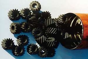
builders, too. The Slant 6 oil pump gear is pretty small, (1 1/8 inch
OD) but was adequate for the original design. A Slant 6 with a stock
pump running 30W oil and 45 pounds of pressure will run forever at
normal driving speeds. But a racing engine with a high-volume pump,
50W oil and 65 pounds of pressure really loads that little gear at
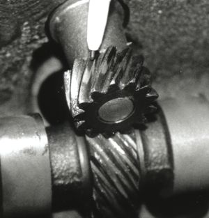
6000 rpm! The gears just don't snap; the teeth wear down drastically,
then eventually one breaks and that's all she wrote. Failed oil pump
gears show heavy wear on all the teeth, and even some
“good” used gears showed noticeable wear.
We
discovered that this problem is not new, nor is it confined to the
Slant 6. As we shall see later, it is a concern for many other engine
builders, too. The Slant 6 oil pump gear is pretty small, (1 1/8 inch
OD) but was adequate for the original design. A Slant 6 with a stock
pump running 30W oil and 45 pounds of pressure will run forever at
normal driving speeds. But a racing engine with a high-volume pump,
50W oil and 65 pounds of pressure really loads that little gear at
6000 rpm! The gears just don't snap; the teeth wear down drastically,
then eventually one breaks and that's all she wrote. Failed oil pump
gears show heavy wear on all the teeth, and even some
“good” used gears showed noticeable wear.
To arrive at these conclusions, we first gathered data from many racers with a questionnaire and interviews. We used data from both failed engines and those without failure. This was put into a "failure matrix" shown on the following page (apologies for typos). We were looking for a common thread through the matrix, which might show a particular pump being suspect, or a certain condition that was common. At first the results seemed inconclusive, but our later findings showed it made a lot more sense if we looked for combinations of factors.
We inspected pumps from various manufacturers and compared gears looking for any critical differences, but nothing appeared to be obviously wrong. I set up a dummy engine with just a crank, cam and oil pump to check the gear relationship and to see if the cam would try to “climb” the pump gear and change the mesh. It turned out that the drag from the pump actually pushes the cam back to the rear of the engine (just like it was designed to, I suppose). Gears were hardness tested (more on this later) and measured for differences in diameter and tooth profile. Again, no obvious evidence appeared.
At this point I started to ask some professional opinions of the problem. I contacted the following people:
Dick Gordon, an industrial parts manufacturer and former stock-block powerboat racer who's experienced this problem before.
John Beardmore, a senior engineer at GM with many patents, much engine design experience, and a drag racer.
Tom Langdon, former GM engineer who runs "Langdon Stovebolt", and a world-class authority on inline engines.
 Jim
Fawcett, GM engineer who worked on the modern transition to roller
cams in production engines and the resulting gear
problems.
Jim
Fawcett, GM engineer who worked on the modern transition to roller
cams in production engines and the resulting gear
problems.
Phil Mclain, professional engine builder and my partner in our big-block Dart bracket racer.
Doug Dutra talked to Doug Holt at Pacific Heat Treating and chased down Mike Osterhaus at Melling Tool. Melling makes many of the Slant 6 replacement pumps and parts we are using today.
As expected, everyone didn't agree on all points, but enough common ground was found to get an understanding of the situation. Here’s what we learned with their help:
 The
Slant 6 oil pump is a typical design where the pump is driven by a
gear off the camshaft. Other engines use the same setup, but the
distributor gear is used to drive the pump through a shaft, so the
distributor gear is really the oil pump drive gear. This gear type is
called a "right-angle helical drive" and is used primarily for cost
and component packaging reasons, not because it is the best design.
Gear engineers seem to hate it. The gears are called "point-contact"
which means there's very little surface area on the teeth
transferring the power, and the strain on the gear teeth is high.
Also the gear surfaces are constantly sliding, which results in
friction and subsequent wear. From what we can gather, the pump (or
distributor) gear is designed to be softer and wear out first, saving
the cam. It's called a "sacrificial" gear.
The
Slant 6 oil pump is a typical design where the pump is driven by a
gear off the camshaft. Other engines use the same setup, but the
distributor gear is used to drive the pump through a shaft, so the
distributor gear is really the oil pump drive gear. This gear type is
called a "right-angle helical drive" and is used primarily for cost
and component packaging reasons, not because it is the best design.
Gear engineers seem to hate it. The gears are called "point-contact"
which means there's very little surface area on the teeth
transferring the power, and the strain on the gear teeth is high.
Also the gear surfaces are constantly sliding, which results in
friction and subsequent wear. From what we can gather, the pump (or
distributor) gear is designed to be softer and wear out first, saving
the cam. It's called a "sacrificial" gear.
We had acquired a selection of both good and bad pump gears, new and used, and had these tested for hardness. All tested between 23 and 27 on the Rockwell "C" scale. For comparison, we tested two GM distributor gears believed to be from a Pontiac and a Buick and these tested 32 and 29 respectively.
Doug
came up with the Chrysler cam gear specs. which called out 48-52
Rockwell, confirming the "sacrificial" theory. However it must be
reported that when we did test a cam gear, it didn't appear to be any
harder than the pump gears. We need to figure out why the pump gear
always seems to wear out first. Is it just because the pump gear is
smaller?
(Oil pump gear is 1 1/8 OD w/ 13 teeth, the cam gear is 1 3/4 OD
w/ 13 teeth)
As stated earlier, the load on the pump gear increases a lot under racing conditions. The finish on the gear is important because little ridges on the tooth face contact surface act like cutters, and the sliding action creates friction, which increases with RPM. Cutting a helical gear is pretty sophisticated compared to normal gear "hobbing" and some cam grinders and gear makers may not have the resources to do a perfectly smooth surface. Also note that the metallurgical properties and hardness of the gears are critical for long wear life. We are working to find out if the material and the heat treatment process originally developed by Chrysler are still being used. It's a lot more complicated than we ever thought and even professional designers have problems getting everything to work well.
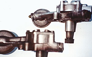 On
most engines the distributor / oil pump drive gear is easily
inspected by pulling the distributor, but on the Slant 6 the pump
should be removed in order to get a good look at the gear. Since it
is an external pump, the oil pan doesn't need to be pulled, and
that's good. However, on A-body Mopars the pump is difficult to
remove due to the close proximity of the frame K-member (Catch 22)
and a hi-volume pump has an even thicker housing, which will make it
even harder to remove. The pump removal problem bears study because
it would be very beneficial to pull the pump and inspect the gears
periodically.
On
most engines the distributor / oil pump drive gear is easily
inspected by pulling the distributor, but on the Slant 6 the pump
should be removed in order to get a good look at the gear. Since it
is an external pump, the oil pan doesn't need to be pulled, and
that's good. However, on A-body Mopars the pump is difficult to
remove due to the close proximity of the frame K-member (Catch 22)
and a hi-volume pump has an even thicker housing, which will make it
even harder to remove. The pump removal problem bears study because
it would be very beneficial to pull the pump and inspect the gears
periodically.
The
pump itself contributes to the source of the gear load and
high-volume pumps are of questionable benefit. Many engine builders
like them for "insurance", but there is a downside. 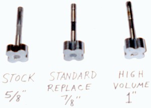 Original
stock pumps had a rotor thickness of 5/8". A "standard replacement"
pump from Melling measures 7/8" - a 40% increase. A high-volume pump
has 1" thick rotors - a 60% increase. All these pumps use the same
small drive gear. Thicker impellers have some affect on the power
input needed to drive the unit and results in more load on the gears.
All the while, the relief valve is still the stock size and may not
bleed off big impeller volume / pressure as quickly as needed. In a
stock engine, the relief valve is open at low RPMs, not too far above
idle. Truth is that the stock pump’s impeller was already
designed oversize so it could deliver oil under extreme conditions,
such as high heat and thin oil. A stock-volume pump may be all many
racers need, unless bearing clearances are set real loose or other
oil system demands are placed on the engine, like turbo oiling, a
remote oil cooler or special filters.
Original
stock pumps had a rotor thickness of 5/8". A "standard replacement"
pump from Melling measures 7/8" - a 40% increase. A high-volume pump
has 1" thick rotors - a 60% increase. All these pumps use the same
small drive gear. Thicker impellers have some affect on the power
input needed to drive the unit and results in more load on the gears.
All the while, the relief valve is still the stock size and may not
bleed off big impeller volume / pressure as quickly as needed. In a
stock engine, the relief valve is open at low RPMs, not too far above
idle. Truth is that the stock pump’s impeller was already
designed oversize so it could deliver oil under extreme conditions,
such as high heat and thin oil. A stock-volume pump may be all many
racers need, unless bearing clearances are set real loose or other
oil system demands are placed on the engine, like turbo oiling, a
remote oil cooler or special filters.
 Heavy
viscosity oil like 50W also puts a real strain on the system,
especially when it's cold. Again, thicker oil seems like more
insurance but the increased gear load it generates is bad news. The
same can be said for high oil pressure. How much pressure is really
needed is subject to opinion and the classic 10 psi per 1000 RPM rule
is not cast in concrete. The pump's relief valve can be adjusted to
set the pressure where you want it. Some racers use synthetic oils
and their stable viscosity and friction fighting properties may help
reduce gear loads, making it worth the extra cost. Anything you can
do to reduce the load on the pump gear is worth looking
into.
Heavy
viscosity oil like 50W also puts a real strain on the system,
especially when it's cold. Again, thicker oil seems like more
insurance but the increased gear load it generates is bad news. The
same can be said for high oil pressure. How much pressure is really
needed is subject to opinion and the classic 10 psi per 1000 RPM rule
is not cast in concrete. The pump's relief valve can be adjusted to
set the pressure where you want it. Some racers use synthetic oils
and their stable viscosity and friction fighting properties may help
reduce gear loads, making it worth the extra cost. Anything you can
do to reduce the load on the pump gear is worth looking
into.
We see a lot of evidence that other engines have also had this problem. The recent Chevy 6-cyl book says that many of their racers stay away from high-volume pumps because it “only adds stress to a weak drive design”. Ford engines may snap off the pump drive shaft with a hi-volume pump so a special hardened shaft is available. Same with Mopar V8’s where the pump gear is huge but a special pump drive shaft is recommended for racing engines. Speed equipment catalogs such as Summit, Jeg’s and PAW list lots of distributor gears, including bronze alloy gears. The PAW catalog states “bronze gears for use with high-volume pumps”. Has anyone ever used these? Bronze gears are interesting but may not be available for Slant 6’s, we are still looking for some to test. The January ’02 issue of Car Craft magazine has an article on distributor gears that is well worth reading in order to get more info and ideas but it seems like we still have more questions than answers so keep the data coming our way!
 To
summarize, the major factors that put load on the gear are: pump size
/ volume, oil pressure, oil viscosity and RPM. Since we need RPM to
make horsepower, we have to look at the other factors in order to
reduce the gear load. Anything that reduces gear tooth contact
friction is also helpful, such as gear alignment, better gear finish
and better lubrication. We continue to collect data (broken parts)
and talk to professionals who may have other solution ideas. We have
accumulated several tips from racers and would appreciate any other
ideas from our readers for a follow-up article, which will cover all
the gear failure prevention ideas and things to check / adjust to
help avoid this problem.
To
summarize, the major factors that put load on the gear are: pump size
/ volume, oil pressure, oil viscosity and RPM. Since we need RPM to
make horsepower, we have to look at the other factors in order to
reduce the gear load. Anything that reduces gear tooth contact
friction is also helpful, such as gear alignment, better gear finish
and better lubrication. We continue to collect data (broken parts)
and talk to professionals who may have other solution ideas. We have
accumulated several tips from racers and would appreciate any other
ideas from our readers for a follow-up article, which will cover all
the gear failure prevention ideas and things to check / adjust to
help avoid this problem.
In the last issue, Bernie
Kuschel reviewed his SL6 oil pump (OP) gear failure data collection
findings. On many failed samples tested, the OP gear surface finish
and hardness was suspect. We saw extensive wear on the OP gear teeth
and little to no wear on the cam gear. Most failed samples looked as
if the OP gear wore, then “stripped”, which then chipped up
the teeth on the cam gear.
A  few
things could cause this:
few
things could cause this:
* The OP gear material is too soft.
* There is not enough oil on the gears to prevent metal-to-metal contact & wear.
* The cam gear’s tooth surface is much harder or has a rough surface finish.
* The gears do not have proper “mesh” so there is heavy load on a small contact spot.
We set
out to see if we could make some changes / improvements to address
all these issues. Our hope is if we address all the suspected causes
of gear failure, we will prevent or reduce the number of failures we
hear about (even if we do not fully understand the causes).
 To
address the surface hardness issue, we talked to a professional heat
treater. They ran a few gear samples through a
“carbonizing” heat treatment process. This was done to make
the OP gear tooth surface harder, while keeping the inner core of the
gear soft. A soft core will reduce the possibility that the gear
would shatter or split along the keyway. What started as a surface
hardness tested at 20-22 Rc, .003 to .005 deep, was heat treated to
40-42 Rc hardness, .020 to .025 deep. This process caused the inner
gear hole diameter to get a bit smaller so if you have one of these
sample gears, lightly sand the inner hole (ID) prior to installing
and inspect it closely. No high spots are allowed on the gear’s
ID walls. (High spots will show up as shinny spots.) To install an
oil pump drive gear onto the pump shaft, heat the gear and freeze the
shaft / pump assembly to make it easier to press on the
gear.
To
address the surface hardness issue, we talked to a professional heat
treater. They ran a few gear samples through a
“carbonizing” heat treatment process. This was done to make
the OP gear tooth surface harder, while keeping the inner core of the
gear soft. A soft core will reduce the possibility that the gear
would shatter or split along the keyway. What started as a surface
hardness tested at 20-22 Rc, .003 to .005 deep, was heat treated to
40-42 Rc hardness, .020 to .025 deep. This process caused the inner
gear hole diameter to get a bit smaller so if you have one of these
sample gears, lightly sand the inner hole (ID) prior to installing
and inspect it closely. No high spots are allowed on the gear’s
ID walls. (High spots will show up as shinny spots.) To install an
oil pump drive gear onto the pump shaft, heat the gear and freeze the
shaft / pump assembly to make it easier to press on the
gear.
There continues to be a lot of
debates about how much oil actually gets onto the oil pump drive
gears. You would think that the splash off the crank & rods would
deliver plenty of oil to the gears but some argue that this is not
true, especially when a windage tray and crank scraper is used. A
number of racers have developed ways to make sure extra oil is placed
right onto the gears. One method is to simply drill a hole through
the block’s main oil galley “pocket” and press in a
small roll pin or tube with a .030 hole to direct a stream of oil
directly onto the gears.

A similar method uses a
special hollow bolt
& tube assembly, bolted into the
unused block “pocket” where the oil pump mounts. A small
“anti-siphon” or standoff tube is then used to connect
& pressurize that pocket. The standoff tube can be installed in
the oil pump or in the block  pocket
but be sure the tube extends to the top of the cavity. This will
prevent the oil from draining out of the main galley after shutdown
(oil drain back).
pocket
but be sure the tube extends to the top of the cavity. This will
prevent the oil from draining out of the main galley after shutdown
(oil drain back).
This delivery tube system sprays pressurized oil right onto the gears, just before they contact each other. You will need a “6 hole” oil pump if you plan to do this modification and it takes some extra work but this ensures that lots of oil is placed on those gears, right where it is needed.
Gear tooth surface quality is another overlooked area of concern. If you inspect a few gears and cams, you quickly see that the surface quality will range from pretty smooth to real rough. On the OP gears we recently heat treated, time was spent lapping the gear tooth face smooth before doing the case hardening.
 The
lapping process can also be done on the cam during a trial assembly
by installing the oil pump to cam and using fine lapping compound
rotated onto the gear teeth. High spots and rough surfaces will
quickly appear and can be lapped-out of both gears. A visible contact
pattern will also appear and should be centered on the gear teeth.
Adjust this pattern if needed by moving the OP gear’s position
on the oil pump shaft. Additional tooth contact and gear backlash
adjustments can be made if the stem of the oil pump is made smaller
to allow upward pump movement. Clean both gears completely when the
lapping operation is finished and use assembly lube on the gear teeth
upon final installation.
The
lapping process can also be done on the cam during a trial assembly
by installing the oil pump to cam and using fine lapping compound
rotated onto the gear teeth. High spots and rough surfaces will
quickly appear and can be lapped-out of both gears. A visible contact
pattern will also appear and should be centered on the gear teeth.
Adjust this pattern if needed by moving the OP gear’s position
on the oil pump shaft. Additional tooth contact and gear backlash
adjustments can be made if the stem of the oil pump is made smaller
to allow upward pump movement. Clean both gears completely when the
lapping operation is finished and use assembly lube on the gear teeth
upon final installation.

Some of the other gear failure prevention measures we have seen used are:
* Add a positive cam stop or “button” to the timing chain cover to prevent the cam from moving forward. (Cam “walk” moves the contact pattern off the tooth.)
* Enlarging and deburring all the oil system passageways and the oil pump cavities.
* Avoid the use of high volume / high-pressure oil pumps. Limit your oil pressure.
 During
our investigation we inspected a lot of oil pumps and saw a number of
differences. One significant difference was the design of the pump
rotors. Most pump rotors have large rounded “clover leaf”
looking lobes while others used a star shaped “Georotor”
assembly. The factory Mopar pump and the Melling units had the
rounded lobes; the Dynagear and “offshore” brands had the
sharper looking lobes. (I am told this is a Ford rotor design.) Of
interest is the fact that when you turn each pump/rotor type by
hand,
the star shaped lobe design feels easier to turn. (Yes, both pumps
had the same 7/8 thick rotor assembly.) At this point, this is just
an observation but it is something we would like to do additional
testing on. You may want to keep an eye out for the other style pump
rotors. (The two small pump cover humps had flat tops on the star
shaped rotor pumps Dutra found.)
During
our investigation we inspected a lot of oil pumps and saw a number of
differences. One significant difference was the design of the pump
rotors. Most pump rotors have large rounded “clover leaf”
looking lobes while others used a star shaped “Georotor”
assembly. The factory Mopar pump and the Melling units had the
rounded lobes; the Dynagear and “offshore” brands had the
sharper looking lobes. (I am told this is a Ford rotor design.) Of
interest is the fact that when you turn each pump/rotor type by
hand,
the star shaped lobe design feels easier to turn. (Yes, both pumps
had the same 7/8 thick rotor assembly.) At this point, this is just
an observation but it is something we would like to do additional
testing on. You may want to keep an eye out for the other style pump
rotors. (The two small pump cover humps had flat tops on the star
shaped rotor pumps Dutra found.)
Another interesting piece of
information is that Melling told us that they are discontinuing the
use of the keyway on their pump shaft to gear interface. They feel
that the added key is “overkill” and adds cost to the unit.
Now is the time to get some Melling rebuild kits if you like the
keyed gear to shaft pump design.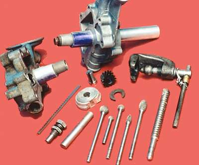
Note that it is possible to visually check for cam gear wear by periodically pulling out the distributor and inspecting the cam’s gear teeth below. The cam’s gear teeth can be seen through the distributor’s mounting hole opening when using a bright light.
As always, please forward any info. or observations on oil pumps or gear failures so we can pass the information along to others.

Copyright - 2002 Slant Six Racing News and Doug Dutra. No reproduction without permission.