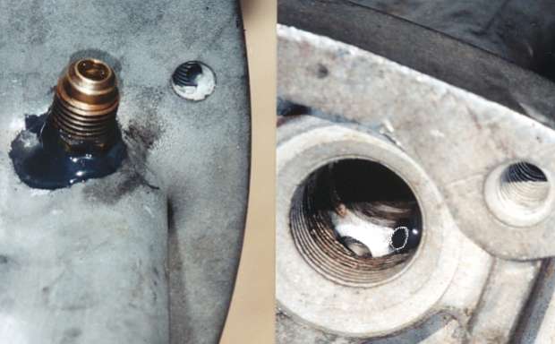
Here is a view if the SL6 engines oiling system and passageways.
Our goal will be to get the system to flow the greatest amount of oil with the lease amount of passageway restriction. High flow at lower pressure uses less HP and keeps the oil pump drive gear "happy".

Take note on how the block is drilled from the main bearing, up past the cam bearing and into the main oil gallery. Most of our work will be around these passages. (4 total, one for each main bearing)
This drawing does not show the fact that these drilled oil passages intersect with the bottom of main bearing cap bolt hole, on the camshaft side. The passageway can be "choked-off" if longer main studs or main bolts are installed.
The best way to check these passages is to drill through them with a 5/16 (.312) long shank drill, with the cam side main bolt / stud installed. ( I have a spacer that is the same height as the main cap, it's really a piece of an old SL6 main cap)


You will find that the drill will hit the sides of the cam bearings so I do the drilling before installing new cam bearings. Try to get the drill to deflect off the bearing's shell and cut as much material off the engine block as possible. The goal is to open-up the passageway under the bearing so the new cam bearings do not restrict oil flow, once they are installed.
On high reving engines, I go as far as chamfering the back-side of the new cam bearings to minimize this "pinch point".

Once you have the drill going all the way thru and into the main oil gallery, it is a good idea to check those intersection points. Remove the front and rear gallery plugs and use a bright light at the oil pump mounting pocket, so you can see how clean and "centered" this intersection point is.


The oil passage holes leading to mains #1 & 4 are right near the end of the gallery and can be seen and deburred (radiused) easily, once the plugs are removed. You can see about 1/2 of the #4 passage hole entrance, just beyond the threads, in the close-up photo on the right. The white area around the hole is fresh cut aluminum (alm. SL6 block) to remove the sharp edge and create a funnel shape, to help the flow of oil around the corner and into the passage.

The intersection points for mains #2 & 3 are deeper in the gallery and difficult to see... and even harder to deburr. Stick the drill through the passage and "backlight" it, to see if the whole drill point is visible. I see many blocks were the drilled oil passageways only partially breaks-out into the gallery, causing restriction and oil flow problems to the mains that need the most oil flow. (mains #2 & 3 have to supply 2 connecting rod bearings, mains 1 & 4 only "feed" oil to 1)
I have a long extension that allows me to reach those passageway intersection points with a "ball burr" and radius the entry by "feel". We have considered drilling access holes, right into the side of the block's main gallery, then threading the hole and installing pipe plugs, in order to get better access and accuratly open-up the areas of concern.
The next sharp corners to "blend" are found where the oil pump mounts to the block. The sharp edges of the casted pocket should be opened-up and "blended" where the drilled gallery passages break into the pocket.

That does it for the the engine block but there is still work to do inside the oil pump (port and "blue print" the pump) and at the crankshaft.
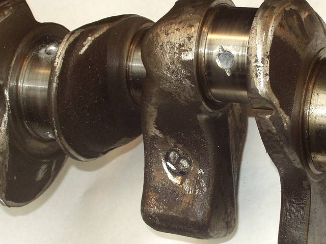
It is a good idea to drill through all the cross-holes in the crankshaft, to be sure those holes are clean and smooth. Also, radius the ends, so the oil can flow in / out smoothly.
I hope this info. is helpful and solves your bearing failure problem.
DD (a responce to a Privet Message asking about early bearing failure)


