Slant Six Forum
https://slantsix.org/forum/

Twiggy - Long Rod Aluminum Block Engine Build-up
https://slantsix.org/forum/viewtopic.php?t=23948
Page 12 of 25

Author:  Doctor Dodge [ Fri Aug 24, 2007 7:15 am ]
Post subject:  Timing Chain Cover...

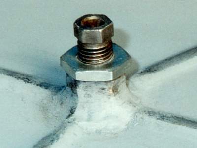
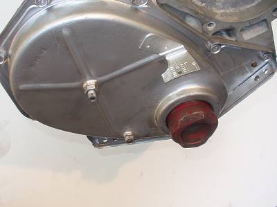
I modified the timing chain cover by adding a cam stop.
I have a special punch that screws into the front of the cam and "punches" the center-point where the hole for the cam stop needs to be drilled. I weld-on a nut and use a rocker arm adjusting screw with a lock nut for the actual cam stop.

Image

The only other mod. to the "later" cover (with the weld-on timing tab) was to open-up the dowel pin receiver holes so the cover "self centers" during installation.
The aluminum / nylon top cam gear was installed at 4 degrees retard per the eariler posts and the cover was installed with a new seal and factory gasket. I use an old hub off a scrap balancer to center the cover as the bolts are tightened.
DD

Image

Author:  Doctor Dodge [ Tue Aug 28, 2007 9:25 pm ]
Post subject: 

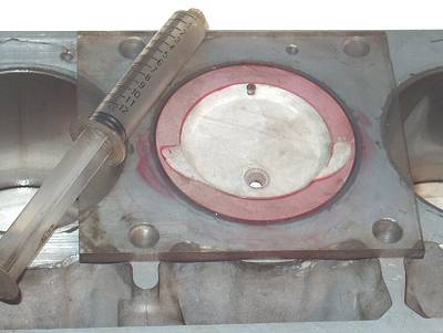
I had a chance to "cross-check" some of the chamber and dish volumes, the static compression came-out at 9.18 so everything is a "go".

Having the piston sticking out of the block sure made it easy to check the piston dish volume!
DD
Image

Author:  AnotherSix [ Wed Aug 29, 2007 11:00 am ]
Post subject: 

Speaking of chambers.....?

Author:  1974duster kev [ Sat Sep 22, 2007 11:04 pm ]
Post subject: 

I wanna hear of or see this bad boy run. get some videos once it's goin for us doc.

Thanks, Kevin

Author:  aluminum6 guy [ Fri Sep 28, 2007 3:04 pm ]
Post subject:  Re: Twiggy - Long Rod Aluminum Block Engine Build-up

Quote:
I am starting to assemble another Slant Six engine and figured I would document the process as the engine goes together.

Seeing there is a lot of interest in "Eileen", the stroker SL6 engine build-up, I decided that this engine also needed a name. So based on the fact that this will be a light weight engine with long (thin) 198 con rods, Twiggy came to mind.
(will this engine be like the thin, light weigth super model of the 60's or will this Alm. Block SL6 break like a dry twig if I build to much power into it?) :roll: :wink:

Naming an engine, or a car for that matter is not something I usually do so this is a "first" for me. This will also be the first long connecting rod Aluminum Block SL6 I have built.

My hope is to show some assembly tips as move thru the build-up. Comments and questions are fine. I will do my best to focus in on SL6 specific details.

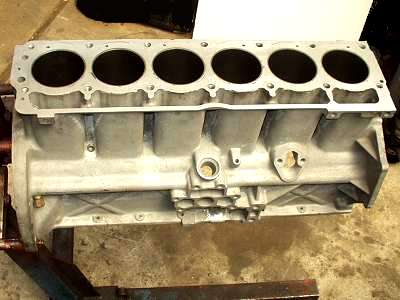
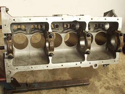
So here is where we start.... with the empty engine block.
For you sharp-eyed Slanters, what is different about this Alm. SL6 block??
DD
Image
Image
Dart 270 asked one of my questions about cooling, is this going to be a drag engine? With the increase in stroke and compression, what kind of cylinder pressure are you expecting & how will that effect axial loading of the crank area? Have you considered the main bearing cap load due to the increase in compression and stroke? As it stands now, it was engineered and tested for 8.21 to 1 compression. The main bearing cap screw is a 1/2" x 13 fastner with standard 60 degree threads. It is torqued to 50 lb-ft and produces an axial load of aproximately 7500 lbs. The load in this area is limited because the aluminum bearing area under the upper bearing cap is only approximately .9 square inches. Breakage starts to occure at 60 lb-ft torque or 9000 lb axial load. Because of it's smaller size and lesser load area, it cannot hold the 10,000 lbs. ( the yeald point of die-cast aluminum) of axial load that the head bolts can hold. Good Luck. Looking forward to your build.

Author:  Doctor Dodge [ Sat Oct 06, 2007 10:16 am ]
Post subject: 

Racing season is now over, it's time to finish this engine build-up.

As for the intended use for Twiggy, high performance street use w/ some limited drag strip action.
Quote:
... The main bearing cap screw is a 1/2" x 13 fastner with standard 60 degree threads. It is torqued to 50 lb-ft and produces an axial load of aproximately 7500 lbs. The load in this area is limited because the aluminum bearing area under the upper bearing cap is only approximately .9 square inches. Breakage starts to occure at 60 lb-ft torque or 9000 lb axial load...
Looks like you have done your homework!
Yes, excessive loading of the bottom-end is a concern. The only change on this build is to use special ARP main studs and to fully thread all the maim bolts to their full depth. This should help support some additional load but you are correct to say that the torque used on the mains has to be limited to 60 ft lbs.
See this article for more info.:
http://www.slantsix.org/articles/ARP-st ... um-arp.htm
DD

Author:  Doctor Dodge [ Sat Oct 06, 2007 7:35 pm ]
Post subject: 

Quote:
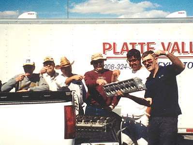
C'mon, guys! Are your collective memories that short? Don't you rememeber that pic awhile back of Doug posing with one of the very few pre-production AL heads in his grubby mitts?...
Roger
You have a good memory, Twiggy will get one of the early factory prototype aluminum heads.
DD
Image

Author:  slantzilla [ Sat Oct 06, 2007 7:40 pm ]
Post subject: 

Quote:
Quote:
C'mon, guys! Are your collective memories that short? Don't you rememeber that pic awhile back of Doug posing with one of the very few pre-production AL heads in his grubby mitts?...
Roger
You have a good memory, Twiggy will get one of the early factory prototype aluminum heads.
DD
Image
Doug, who all is in that picture? I see you and Steve Magnate, and I think Mike. I know that is Mike's trailer. Was that Vegas or a Redding race? :D

Author:  Doctor Dodge [ Sat Oct 06, 2007 7:52 pm ]
Post subject: 

The photo was taken at the first Mopars at the Strip, Las Vegas event in 2004.
From left to right:
Mike Jeffrey
Dave Mueller
Rick Valent
Charlie Thompson
Steve Magnate
and myself

Author:  slantzilla [ Sat Oct 06, 2007 9:05 pm ]
Post subject: 

Thanks Doug! :D

Author:  terrylittlejohn [ Sun Oct 07, 2007 3:37 am ]
Post subject:  twiggy

doug are you holding that head with one hand :?:

Author:  Doctor Dodge [ Sun Oct 07, 2007 8:56 am ]
Post subject:  Re: twiggy

Quote:
...are you holding that head with one hand :?:
Yes, there are no strings attached!
This head weighs 32 lbs with no hardware.

I did some moderate porting work to it so it is now slightly lighter then that.
DD

Image

Author:  DusterIdiot [ Sun Oct 07, 2007 9:03 am ]
Post subject:  Is that the head?

You brought up to Salem for the Oregon crowd to 'look at'?

If so I can vouch that you couldn't believe it really was a cast head, without the valves and hardware it was as light as a feather (compared to a stocker chunk of iron...)

thanks for sharing Doc, hope it all comes together...(how much is the mill going to weigh over all when you're done?) :wink:


-D.Idiot

Author:  Doctor Dodge [ Sun Oct 07, 2007 9:14 am ]
Post subject: 

Quote:
...how much is the mill going to weigh over all when you're done?
The final engine weight is the "Lotto question" of the project. I have carefully watched every ounce of weight going onto this engine so we will see where it ends-up. On paper, looks like somewhere between 300 & 350 lbs.

As for the Alm. head, yes... it is the one I showed you when Allen and I traveled to Salem, OR for the Robertson's Mopar show.
DD

Author:  Doc [ Tue Oct 09, 2007 5:42 pm ]
Post subject:  Head Gasket Alignment

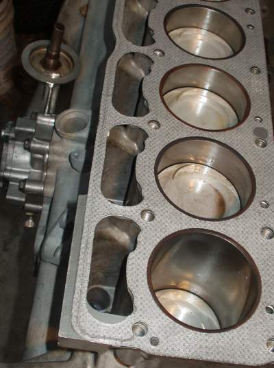
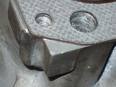
I did a fit check with the head gasket.
Matched it with the block's bores and with the head's chambers. I had to do a small position adjustment to get the gasket perfectly centered. I did this by carefully reaming-out the dowel pin holes in the gasket and then glued-in some filler material so the gasket fits snugly around the dowel pins.
Image

I also put a few location reference marks on the engine block and head to show where everything needs to be when it is assembled.
DD

Image

Page 12 of 25 All times are UTC-08:00
Powered by phpBB® Forum Software © phpBB Limited
https://www.phpbb.com/