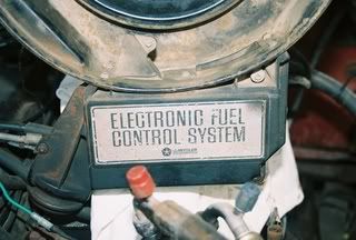
Problem :
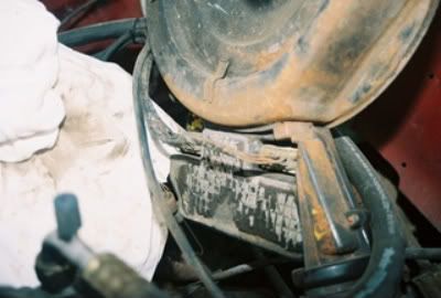
This Truck was running badly, many previous
owners hacked, removed, replaced
components and wiring such that the
computer was not getting all the inputs
it needed to function. Therefore
the lean burn system "defaults"
to get you home timing. The result
high fuel consumption and poor performance.
So bad in fact that the truck
or the system had to go. It was a
lean burn w/o 02 feedback.
There are many ways to do the conversion
this is just one ----
Some may consider this overdone....I agree,,,
had time on my hands, and, I only like doing
things once!
I have visited this site many times and "taken"
away a lot of information. This was an opportunity
for me to "give back"to the forum. Many of you
pros out there know this is a simple conversion.
But, for some, it can be challenging.
For me it was an opportunity to fabricate a
solution and share it with others. Enjoy.
Step 1
I Read info from here (hei section, and FORUM)
regarding reasons to convert, technical advantages,
parts needed, and How To.
Step 2
Ordered "Shop Service Manual" from:
politpaul@yahoo.com
reasonable and professional, "no CD" "paper back original"
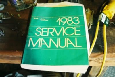
Note: READ YOUR MANUAL!
some electrical diagrams are posted
in the previous post on this subject which relates
to this modification! I will also modify a simple
wiring diagram when finished posting
Step 3
Consulted local Emissions people, and emissions
map on truck to determine if truck would meet
regulations with removal of "EFCS"
Important, a little effort here will save you a
lot of grief later, saving you money and repeat trips to
junk yard looking for those parts you discarded!!!
CONSULT YOUR OWN PARTICULAR STATE/COUNTY
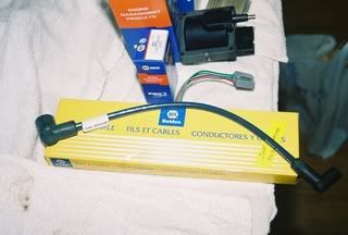
Step 4
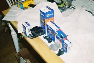
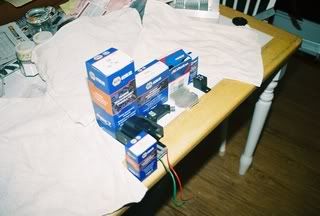
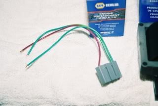
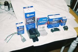
Ordered Parts
NAPA
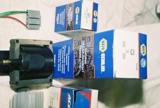
coil napa echlin # IC24
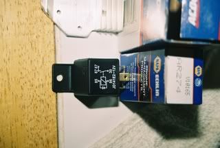
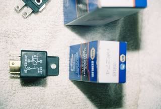
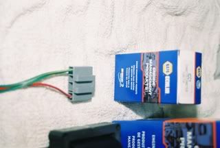
relay napa echlin # AR274
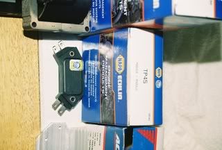
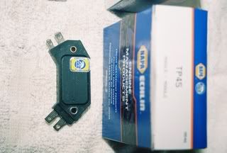
hei module napa echlin # TP45
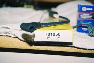
coil wire napa belden # 701050
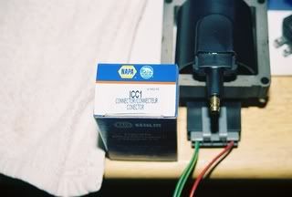
coil connector napa echlin # ICC1
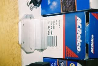
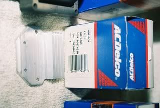
heat sink ac delco # 00212G4
LC01 ACD# 10474610
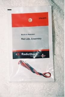
leds radio shack # see pic,,many to choose
from
Some Photo's of the Individual Parts
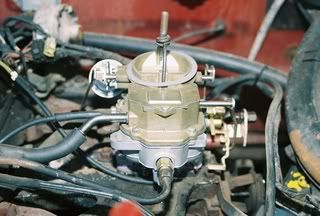
Ordered Carburetor from:
Carburetor Specialist
5715 N Commerce Ct.
Suite 200
Alpharetta,GA 30004-4178
(678)393-1501
My salesman was Greg
Their Part # NC- 108-2404 Carter BBD/DC
Note: These people are expensive but very
competent. They will get you the right carburetor
if you answer their questions.
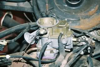
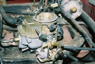
Replaced carburetor on truck with NEW mechanical,
non-computer type BBD No pic of old carburetor
as it was sent to shop in exchange for
the new one. Installed the Carburetor and
used old mechanical electric heated choke to test.
Will probably replace with a mechanical cable type
when conversion is finished.
Step 5
Installed Carburetor - Test to make sure engine
runs correctly.
Ordered Distributor from:
Old Car Parts NW, Inc
1120 SW 16th Street #7
Renton,WA 98057-2639
(206)300-1083
Email ocpnwi@gmail.com
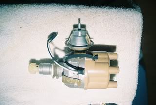
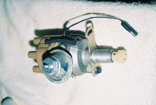
Replaced distributor on truck which was lean burn dual
pickup, non vacuum advance, with Mechanical
Electronic Vacuum Advance
part # 3874714 as suggested on these posts
Your manual may also have a P/N.
See other parts of forum for Distributor variations
and modifications.
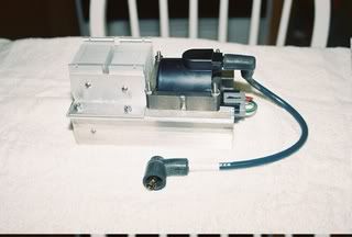
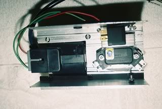
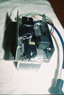
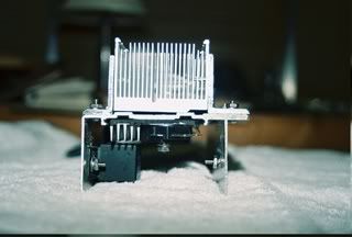
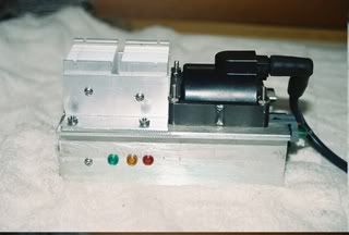
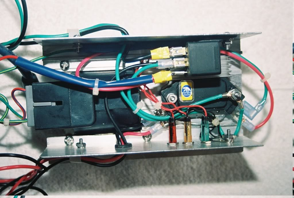
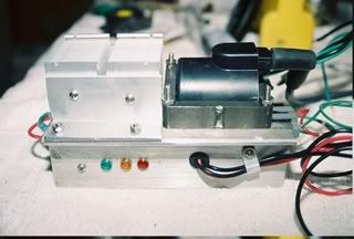
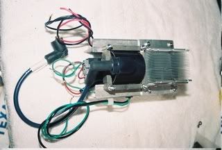
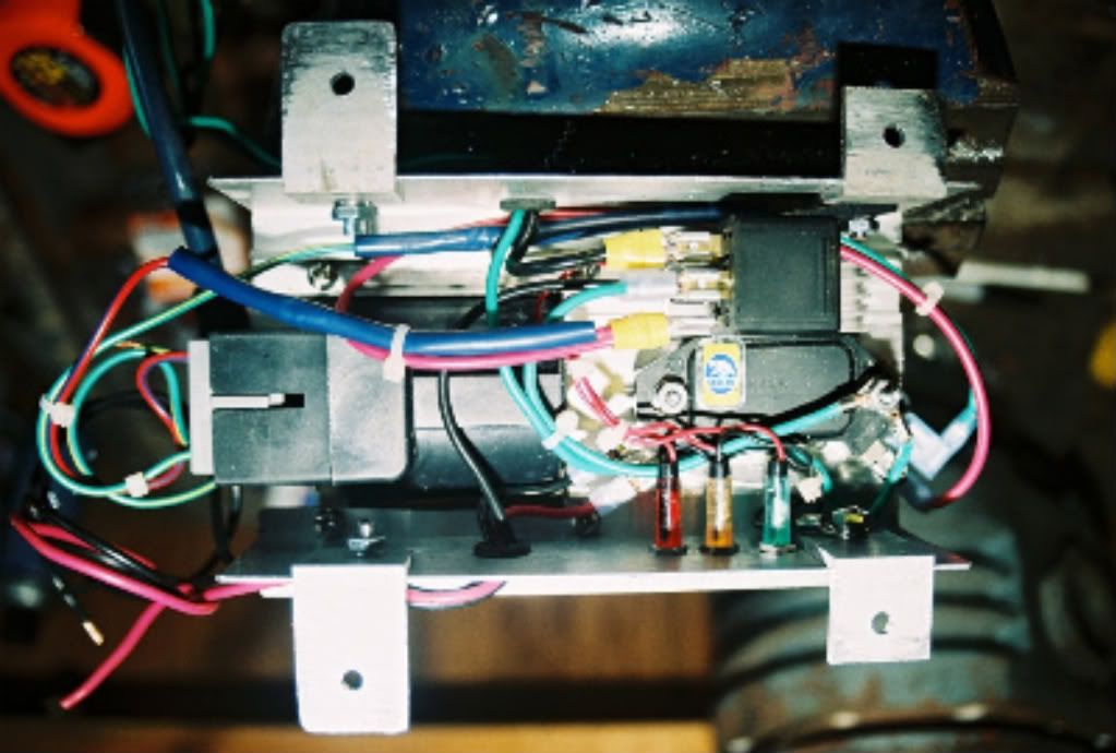
Step 6
Fabricated Unit
Found window or door aluminumchannel
at junk yard.
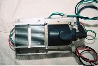
Found heat sink at computer store scrap bin,
came out of desktop computer (would be
lower profile if you can find one
from a server)
Yep, went overboard with heat sink,
"YOU" do not need that much. (personal philosophy,
I OVERBUILD !)
(a little about ht transfer later)
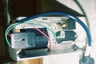
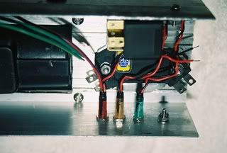
Fabricated the above parts into the channel
Used all stainless steel machine fasteners
fastener sizes machine --6/32 8/32 10/32 10/24
(screws, flat & lock washers & nuts)
Used shrink wrap when splicing
Used insulated connectors and crimped wiring to them #12 #14 #16
Used quality automotive wiring ---#12 #14 #16 copper
Used rubber hole grommets
Used nylon wire holders
fused main power supply to unit , (20A) #12 copper wire
All grounding wires "non-insulated stainless connectors crimped"
Use hi quality automotive electrical tape and tie raps
Note: This is important, PUT 20A fuse assembly
as close to the battery as possible. If there's an electrical
fault in the system or between the battery and the
system the fuse will protect the module and wiring
to the module.
Note: When placing hei unit make sure you place on flat,flush surface
and use the dielectric grease. My hei (napa) had a couple
of plastic placement dowels that i filed off, which then allowed it
to lay flat and flush.
Because of an irregularity in the door/window channel i
selected, i used the GM AC DELCO heat sink so the hei
unit would sit flush to the channel. This is important.
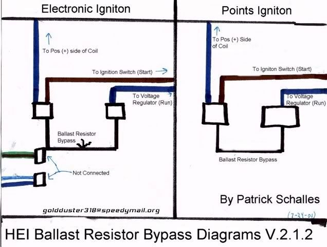
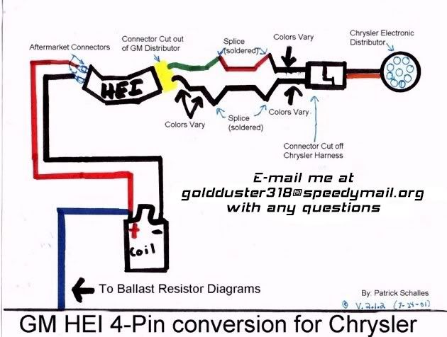
*** Used the following WD's as a guide ****************
Note: THESE ARE NOT MY DIAGRAMS, THEY CAN BE FOUND IN
THIS SECTION AND ON THE NET.
You will find full w/d in your manual and a good w/d for this
conversion in the previous post in this section. Your best
course of action is to GET familiar with Your car/truck
by reading YOUR Owners Manual.
---------- Thanks to those who uploaded them -------
--- Will upload a simple W/D showing led's and pwr relay
when finishing post ----

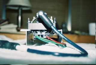
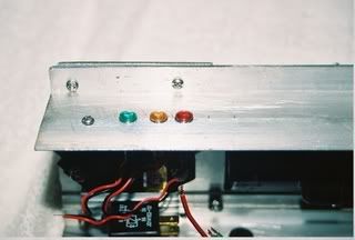
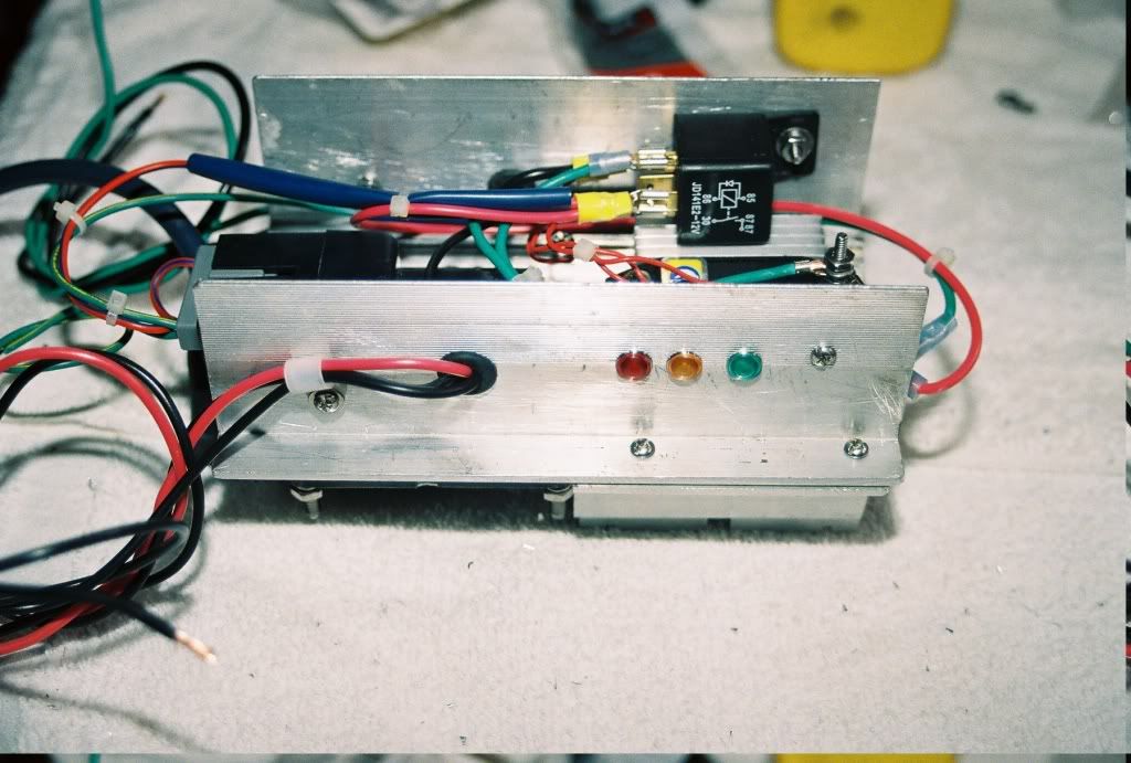
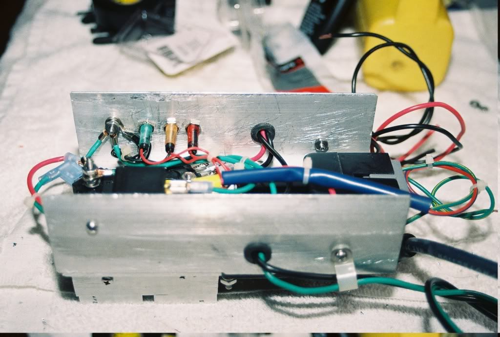
Don't like testing (lazy) so added led lights to tell
me when i have
RED........fused main batt voltage to unit
AMBER....ingition switch on
GREEN....output relay power to coil and hei unit
"NOT REQUIRED FOR UNIT FUNCTIONALITY"
Note: [led's are internally resisted, so you don't have to worry
about installing 12v resistors for the led's]
power consumption of leds will not effect full batt
voltage to relay/coil/hei unit as the draw is
extremely small. Will add wiring instructions for them
as this post matures.
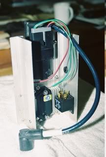
Fabricated tabs to hei module to fit on firewall
http://i1138.photobucket.com/albums/n53 ... 024A-1.jpg
Step 7
Install/ test New Distributor and Ignition Module
Make sure you spend the time to "find" TDC "top dead center"
prior to removing the old and installing your new distributor.
(Many posts here and in your manual will guide you)
Removed old coil, marked +/- wires with pen & masking tape
Removed old Distributor and Installed new distributor,
Notes:found timing slot on NEW distributor
hold down mechanism slightly smaller than the hold down bolt.
Hold down mechanism are different from my stock 83 D-150
and the older version distributor pictured as parts bought
(probably mid 70's). Therefore, used a small round file to
edge out the slot so that the hold down bolt would fit enabling
the distributor to move freely from full retard to full advance
positions. (Didn't take much too accomplish this) Don't panic
if yours is a little tight also, just use the old round file.
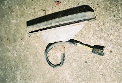
Look at the connector coming from your new distributor.
If its a Dodge/Chrysler it may have (this connector see pic on my
new dist) Don't know the name but it is a male/female prong
socket type. Many 70's and 80's Dodge truck and vans
(turn signal, parking, and stop lites) have this connection.
I simply cut one from some of the junk i have and splice
to wires that came with your new dist. WALLA-A Quick
disconnect. You will find this handy in the future
when removing the dist or the hei module you
just fabricated.
http://i1138.photobucket.com/albums/n53 ... 4-012A.jpg
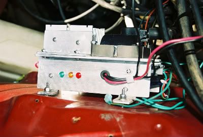
Another quick removal trick, when selecting the fender well site
you r limited by the length of the coil leed to the dist. I
fabricated module mounts so that the hei module could be
removed quickly for repair without fumbling
with the underneath firewall bolts.
http://i1138.photobucket.com/albums/n53 ... 023A-1.jpg
http://i1138.photobucket.com/albums/n53 ... 4-021A.jpg
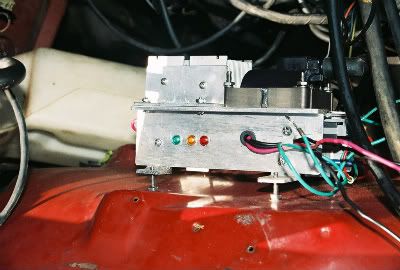
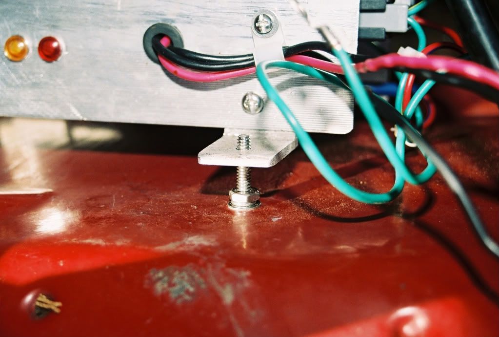
I used stainless fittings because its important to achieve and maintain
good grounding. It won't rust. Keeping the unit away from
fender well allows moisture and small debris to roll under unit.
Complete module install on firewall.
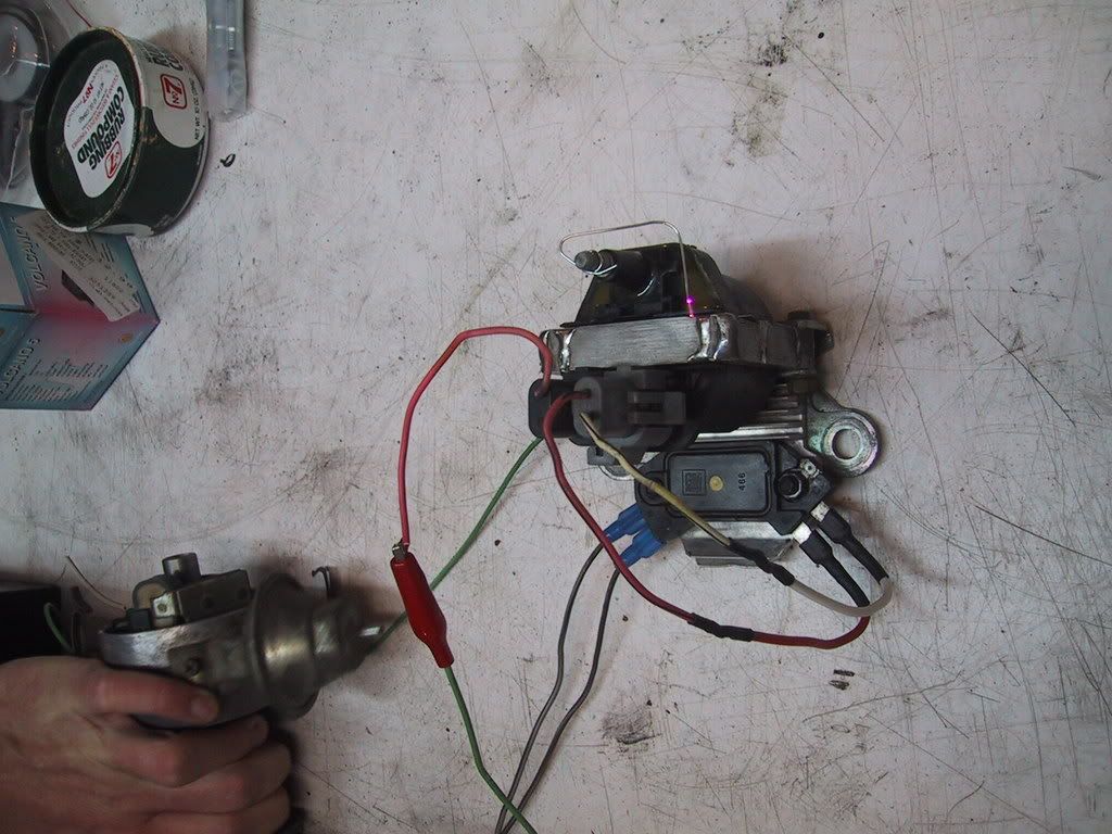
Test Module w/LED Installed:
Make sure module ground wire is connected to GROUND
on module bolt fender well
(fabricate a jumper of #12 copper wire with a couple of alligator
clips).
Connect one end of alligator clip to the 20A fused wire from
pos (+) side of battery. Briefly connect other end to main
12V side of module. This would be the main Input to the
secondary or hi side of the power relay.
You should see the module "RED LED illuminate"
and no others. You should not hear a relay actuation sound.
(RED LED is wired from secondary side relay input to ground
via an internal resistor) Indicating battery availability.
Disconnect jumper from battery
Find (+) coil wire previously marked with masking tape
during coil removal. Connect this wire to the low side of
the power relay.
Turn ignition switch to "ON" "NOT START" position.
This will allow ignition voltage to flow through the
primary side or low side of the relay to ground,
thus actuating the secondary side relay switch.
However since battery power is not connected
via the jumper no RED OR GREEN LED will
illuminate, only the "AMBER LED" illuminates.
You will hear the power relay switch activate.
Turn ignition switch OFF
Reconnect the alligator jumper from the 20A fused
battery power to the HI side or Secondary side of the
power relay
You should see the RED LED illuminated constantly
Turn the ignition switch to ON
You should see the RED LED, AMBER LED and the GREEN
LED illuminated and the sound of the relay actuation.
ALL LED's should remain on!
Start Motor.
Test Module w/out installation of LED's
Testing module without LED's simply connect as
described with LEDS.
Start motor.
If motor runs you can plan your wiring harness
permanent installation.
Note: Assuming you fabricated and wired
the module correctly, installed the carb, and
distributor correctly the engine should run.
Only problem i had was I had to reverse the
wires coming from the Distributor to the hei
module, after that I thought I had a turbo charged
slant/6. Good reason not to permanently
wire anything except module until engine runs.
Final Clean up of wiring harness w/o removal of old EFCS
wiring.
Simply finish hard wiring what you got and clean up the existing
wiring harness.
Final Cleanup of wiring harness with removal of old EFCS
wiring. Following description is what I did. There are many
many possibilities here.
Understand your own vehicles options as they relate to the
electrical,emission,fuel,vacuum etc systems.
Decide what it is you want to be left with at the end of the
conversion.
Once I completed this I opened up the wiring harness
by cutting the harness tape and spreading the wiring
out. For your ignition module you only needed the
ignition wire from the coil and a fused power supply
from the battery as well as good grounding and the
necessary connections to the distributor.
Once you "OPEN" up the wiring harness the layout
of the lean burn system appears straight forward
despite the amount of wiring I planned on
removing.
My plan was to remove "ALL" the lean burn system.
In addition I wanted to remove the electric choke,
electric temperature and oil pressure senders and
gauges. This would leave a pretty sparse and simple
electrical system under the hood.
* working on w/d and resizing pics, processing
more pics, adding links to
load quicker jeff 08/12/11
------ continued --