Slant Six Forum https://slantsix.org/forum/ |
|
New 70 Duster barely starts, and backfires or spews soot https://slantsix.org/forum/viewtopic.php?t=53793 |
Page 4 of 6 |
Author: | killnine [ Fri Nov 15, 2013 10:27 am ] |
Post subject: | |
Quote: A picture of the alternator connections would help, but the wiring sounds correct. The unused hole marked GRND is probably just a threaded hole for a ground wire, which is a good idea to have.
Well that's good news I think. I'll do some tests later. If this really is a 'dual field' alternator then maybe I don't have to buy a new one.The dark wires on FLD and at the regulator should be Blue and they join together in the harness, they should have 12 volts switched by the ignition. The green wire from the regulator should indeed go to the field ground on the alternator, which should not be grounded to the case. You can test that with an OHM meter, remove both field wires and meeter between them and the case, you should see infinet or open on the meter. Again, the wiring sounds fine it is just the type of connectors you are describing that sound a bit off, a picture would prove them. The melted battery connection might have just been a loose connection, or it could have been caused by a bad diode or reversed booster cable connection. It should not have been caused by shorting a gauge lead. Here is a simple video that will show the connections and a simple way to prove that the alternator is working and test the connections. Make sure you only do the test momentarily, and I use the regulator body for ground to prove that it is grounded as well. The regulator ground is important and should really have an extra wire to ground it and the alternator together. http://youtu.be/ZzBbpTtVF-4 
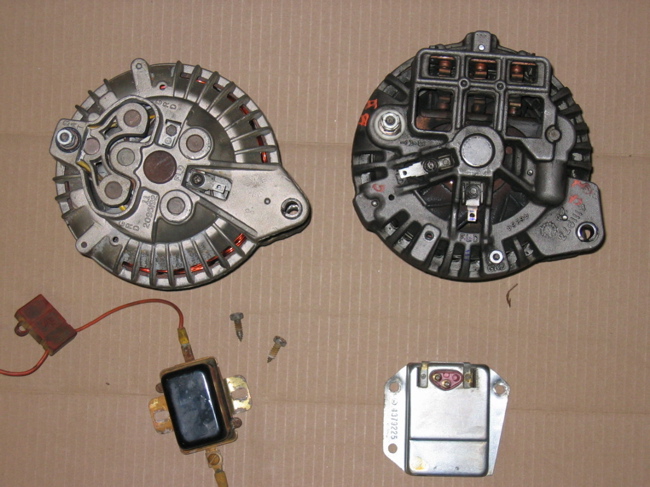
Sorry for the darkness and bad angle, but this is the best pic I have at the moment. ![]() The connectors are the same kind used in these 2 alts, so perfectly normal. ![]() |
Author: | mattelderca [ Fri Nov 15, 2013 10:53 am ] |
Post subject: | |
In the bottom pic, the right side alt and reg can be used together. Same with the left pair. But you cannot mix from side to side. I cannot see the actual green wire terminal in your pic, but it appears that your alternator is a grounded field type and WON'T work with the wiring or regulator in your car. Best way to be sure is to do the check I mentioned and meeter between the case and the two field terminals. Any connection to ground here is the wrong type for the wiring you are describing. |
Author: | killnine [ Fri Nov 15, 2013 11:31 am ] |
Post subject: | |
Quote: In the bottom pic, the right side alt and reg can be used together. Same with the left pair. But you cannot mix from side to side.
With the battery disconnected, I get continuity between the case and the dark wire which normally goes to the FLD terminal. No continuity between the two, or between the green wire and the case.I cannot see the actual green wire terminal in your pic, but it appears that your alternator is a grounded field type and WON'T work with the wiring or regulator in your car. Best way to be sure is to do the check I mentioned and meeter between the case and the two field terminals. Any connection to ground here is the wrong type for the wiring you are describing. With the batter connected and ignition on, I get continuity between the two wires, and between both wires and the case. |
Author: | killnine [ Fri Nov 15, 2013 11:38 am ] |
Post subject: | |
Quote: Quote: In the bottom pic, the right side alt and reg can be used together. Same with the left pair. But you cannot mix from side to side.
With the battery disconnected, I get continuity between the case and the dark wire which normally goes to the FLD terminal. No continuity between the two, or between the green wire and the case.I cannot see the actual green wire terminal in your pic, but it appears that your alternator is a grounded field type and WON'T work with the wiring or regulator in your car. Best way to be sure is to do the check I mentioned and meeter between the case and the two field terminals. Any connection to ground here is the wrong type for the wiring you are describing. With the batter connected and ignition on, I get continuity between the two wires, and between both wires and the case. |
Author: | killnine [ Fri Nov 15, 2013 11:41 am ] |
Post subject: | |
Quote: In the bottom pic, the right side alt and reg can be used together. Same with the left pair. But you cannot mix from side to side.
OK, now measure between the terminals and the case, no continuity between either terminal and the case, but the two terminals have continuity together.
I cannot see the actual green wire terminal in your pic, but it appears that your alternator is a grounded field type and WON'T work with the wiring or regulator in your car. Best way to be sure is to do the check I mentioned and meeter between the case and the two field terminals. Any connection to ground here is the wrong type for the wiring you are describing. |
Author: | killnine [ Fri Nov 15, 2013 11:54 am ] |
Post subject: | |
Quote: Quote: In the bottom pic, the right side alt and reg can be used together. Same with the left pair. But you cannot mix from side to side.
OK, now measure between the terminals and the case, no continuity between either terminal and the case, but the two terminals have continuity together.I cannot see the actual green wire terminal in your pic, but it appears that your alternator is a grounded field type and WON'T work with the wiring or regulator in your car. Best way to be sure is to do the check I mentioned and meeter between the case and the two field terminals. Any connection to ground here is the wrong type for the wiring you are describing. I'm still unsure about the two fields having continuity together, but since either field can send voltage and/or receive ground from the regulator, it seems logical they would be connected together somehow internally. Or am I wrong here and something is still amiss? |
Author: | mattelderca [ Fri Nov 15, 2013 1:39 pm ] |
Post subject: | |
Your all good then! The ignition feed (blue) powers the field coil in the alt. The green wire provides a variable ground through the regulator for the field coil. That's why it's important to have a good ground on the reg. That variable ground the reg provides controls the output voltage of the alt. The blue wire at the reg just tells the reg. what voltage is coming out of the alt. So that part of your wiring is all good. Now you just need to make sure the rest of the wiring and the alt. itself is good. As you say you have a burnt battery terminal on the alternator and it might have a bad bearing or two as it's seized. You can check for a shorted diode by removing the battery wire from the alt. and checking continuity to the case (ground) You should see an open connection. Spinning it by hand should confirm a bad bearing. |
Author: | killnine [ Fri Nov 15, 2013 3:34 pm ] |
Post subject: | |
Quote: Your all good then!
It's not seized, just tested that this morning. I'll test the diode being shorted in a bit. If that checks out then maybe I have a good alternator.The ignition feed (blue) powers the field coil in the alt. The green wire provides a variable ground through the regulator for the field coil. That's why it's important to have a good ground on the reg. That variable ground the reg provides controls the output voltage of the alt. The blue wire at the reg just tells the reg. what voltage is coming out of the alt. So that part of your wiring is all good. Now you just need to make sure the rest of the wiring and the alt. itself is good. As you say you have a burnt battery terminal on the alternator and it might have a bad bearing or two as it's seized. You can check for a shorted diode by removing the battery wire from the alt. and checking continuity to the case (ground) You should see an open connection. Spinning it by hand should confirm a bad bearing. As for it not starting and sounding like the starter is spinning, I really hope now that it's the starter. I was reading the adventures of another poor soul on another forum and he had a similar noise and problem and it turned out to be a messed up timing chain. I'll have to get the wife to turn it over while I listen. It sounds like a starter noise but god only nows. Seems like I need to verify the dizzy gear, that the rotor turns when the crank does, etc. I'll need more tools for all that since I don't have big sockets. Fun times. |
Author: | killnine [ Sat Nov 16, 2013 2:33 pm ] |
Post subject: | |
new starter and starter relay, and it still does the same thing. if I keep the key turned it continues to try to start sometimes without the starter overrun noise but it's a slower crank and not the normal full crank that would start the engine. I just topped off the battery and it was barely in need of a charge, so I don't think there are battery issues. The overrun/spinning/rattling noise is definitely coming from the starter area so it's not the timing chain that's making that noise. I haven't pulled the distributor yet. |
Author: | killnine [ Sun Nov 17, 2013 8:08 pm ] |
Post subject: | |
Well I replaced the starter and starter relay just in case. Continuity checks on all the wiring involved except the ignition circuit inside the dash. Getting voltage in run to the coil. Getting spark at the distributor. Rotor turns when I'm cranking it over. I also jumped the screws on the relay to bypass the ignition switch. I think the starting behavior I'm hearing is normal, or at least it was when I bypassed the ignition switch. It's still not starting, so I'm starting to think there's something even simpler going on. I'm taking a breather and then I'll check the carb again. The filters are full of fuel but I haven't messed with the carb since it first started having this starting trouble and the output terminal on the alternator got melted. I feel like I'm going in a huge circle. I guess you can never really check something off as 'it works', and you have to really verify everything all the time when troubleshooting. I should know that much from working on computer systems. Edit: I should also mention, I had spark that jumped about a half inch at least from the coil wire to the intake bolt, but it was orange. I seem to recall that means it's a weak spark. |
Author: | moparlewellen [ Mon Nov 18, 2013 9:58 am ] |
Post subject: | Distributor |
I haven't read the whole thread but have you checked to make sure that the distributor isn't 180 degrees out? |
Author: | killnine [ Mon Nov 18, 2013 6:26 pm ] |
Post subject: | |
Well a voltage drop test from the battery positive to a number of places, including IGN on VR, coil +, #1 on ECU, wires tied together where the old ballast used to be, alternator blue terminal, bulkhead entry point to IGN RUN Everything has a voltage drop of between 1.9 and 2.4 volts. So now I think it's a matter of tracing the feed voltage in RUN from the alternator/starter relay/fusible links to the ammeter, and then to the ignition switch and fuse box under the dash, as well as the 'junction' under the dash, wherever that is. |
Author: | 64ragtop [ Tue Nov 19, 2013 11:04 am ] |
Post subject: | |
That's WAY too much voltage drop! Should be a few tenths of a volt at most! BC |
Author: | killnine [ Tue Nov 19, 2013 3:41 pm ] |
Post subject: | |
Quote: That's WAY too much voltage drop! Should be a few tenths of a volt at most!
Yeah definitely. I just need to keep measuring and find out where it starts dropping, or where there might be a bad ground. I'm pretty much left with everything under the dash, so that's my goal for tonight.
BC |
Author: | killnine [ Tue Nov 19, 2013 8:19 pm ] |
Post subject: | |
Well, fiddling around under the dash I tested the harness connection for the ignition switch. Every wire that was supposed to have power in the run position does, but has far too much voltage drop. I couldn't get to the internal side of the bulkhead because I don't want to stick my head or hand up that far. I'm scared of black widows. The positive side of the ammeter feed is fine at the bulkhead on the engine side, so no issues with the stock fusible links or anything. Internally on the other side, this is supposed to hit a splice and then feed the ignition switch, but I know that by the time it gets there it's dropping voltage. I am almost 90% sure the issue is in the splice, but I have no idea where to look for that. While I found the white harness connections for the ignition switch wiring, I haven't been able to see where the splice might be. If it's internal at the bulkhead, I don't think I'm going to have the cojones to mess with it until I fumigate the whole car to kill any creepy crawlies. At this point, I would really like to drive this thing, or at least have the option, since I don't have a car, so I'm thinking the immediate best solution would be to rig a 12V temporary 'switched' feed to the bulkhead where the feed would normally come from the ignition switch. This way I can connect this 'switch', get 12V everywhere it's needed in the ignition circuit, and start the car. Assuming this was the issue with starting it to begin with. The ballast resistor in this thing was bypassed, and I tested it and it seems sketchy, so I'm just going to go ahead and install the pertronix flamethrower 3ohm coil so I don't have to worry about it. That might have been part of my problem. Once I had the engine running for a bit, with a bypassed resistor, I might have burnt out the coil enough to cause issues. Since I can't get a switch easily, I think my ignition switch will just have to be a makeshift plug I can stick into the bulkhead to create that feed before I want to start the car. I think just feeding this from the starter relay battery feed would make the most sense. A 10ga wire with a fusible link straight to the starter relay. Later I can put a switch in it so I don't have to connect and disconnect it haphazardly. Anything wrong with this idea? I'm pretty sure people do this all the time anyhow when they make their own ignition and start circuits. By the way, if anyone finds it useful, here's a pretty picture I made. ![]() |
Page 4 of 6 | All times are UTC-08:00 |
Powered by phpBB® Forum Software © phpBB Limited https://www.phpbb.com/ |