Slant Six Forum https://slantsix.org/forum/ |
|
Electronic Ignition System for Lorrie Van Haul https://slantsix.org/forum/viewtopic.php?t=49262 |
Page 5 of 12 |
Author: | JCAllison [ Tue Jul 31, 2012 3:59 pm ] |
Post subject: | |
Quote: I do have the A-1 at the ready..
Hey Dusty, Have been spending the time awaiting the arrival of the Control Module Heat Sink by doing stuff like sharpening the Craftsman Lawn Tractor Blades, and figuring out how to mount all the HEI Electronic Ignition Components. Can't really solidify anything though until the Heat Sink gets here to see how big it is, where it can be mounted, and how to route the Wiring. Quote: Still visiting via cell fone, but am trying to keep up with the servings. (of mule meat)
Just got done looking at the FedEx SmartPost Tracking Website. It says that the package was delivered to the Onalaska Post Office today at 3:15 p.m. Will call the Post Office in the morning to see if they actually HAVE the package, and if they do, will go pick it up. Quote: Hope you are having a good day...
It's been quite tolerable. Have given up on worrying about the delivery. If it happens, it happens. It's just that the whole Heat Sink debacle has been like pulling teeth, if you know what I mean, if you get my drift, if you see what I'm saying. ![]() So how have YOU been? Everything going alright? Hope YOU are well. JC |
Author: | JCAllison [ Wed Aug 01, 2012 12:32 pm ] |
Post subject: | |
Hey All, Wednesday Afternoon Update: Went to the Post Office and picked up the Control Module Heat Sink (HS). A spiffy little unit if ever there was one. The HS has two holes in it through which go the Bolts that hold it to the Control Module (CM). It also have another two holes in it into which fit two small "registering nubs" on the CM. 'The CM likewise has two holes in it the same size, and the same distance apart as the two holes in the HS. The only problem is that the two holes in the HS are too close to the Aluminum Fins and when the upper edge of the CM is hard against the Fins, the holes in the CM don't match up with the holes in the HS. Two things can be done about this. Either drill NEW holes in the PROPER locations, OR cut off one of the Aluminum Fins. Stopped at the Hardware Store on the way back from the Post Office and obtained a package of 3/16" Female Spade Connectors, and two Bolts, two Washers, and two Nuts with which to fasten the CM to the HS. At this time, it is thought that there is going to have to be acquisition of a piece of 1.5 X 1.5 X 1'-0" Angle Iron which will be bolted to Lorrie's Floor, and on which will be mounted the Brackets that hold the HEI Ignition Coil (IC), and the HS, and the CM. Am going to have to go out and check to see if there is room for all this. Once all the modifications are done to the HS, the CM will be mounted on HS. Then the CM/HS Assembly will be fastened to the IC, and THAT whole assembly will be fastened to the Angle Iron bolted to Lorrie's Floor. Once all that is ready, the first thing to do is to install Lorrie's NEW NOS Electronic Distributor. In visualizing THAT process has raised a number of questions. The Teeth on the Gear on the Distributor Shaft HAS to be in the EXACT relationship with the Teeth on the Gear of the Cam Shaft. Lorrie HAD a Standard Points&Condenser Type Distributor (SD), so the first question is about it: With the Number One Piston at PRECISELY Top Dead Center (TDC) at the top of the Power Stroke, if the SD is properly positioned, would not the Rub Block of the Points Set in the SD be right AT the Apex of the Hex Shaped Cam on the SD's Shaft with the Rotor pointing at the Number One Spark Plug Terminal Tower? Presently, the Number One Piston in Lorrie's 225 Slant Six Engine IS at TDC, and the Rub Block of the Points Set WAS sitting on the Apex of the Hex Shaped Cam on the Shaft of the SD, AND the Rotor was pointing to the Number One Spark Plug Terminal Tower. That was, and still is the condition of the Engine when the SD was removed. So the NEXT thing to do is install the Electronic Distributor (ED). It is going to have to be installed in PRECISELY the CORRECT position with the Number One Piston at TDC. Am NOT sure how THAT is done. Am going to have to do the research necessary to find out how to install the ED. Today is pretty much a survey day now that all the Components are here. Will be taking JPGs of them as the project progresses. Will keep you all updated on events as they happen. JC |
Author: | Reed [ Wed Aug 01, 2012 12:45 pm ] |
Post subject: | |
Whenever I am installing the distributor, I out the rotor about 30 degrees counter clockwise from where I want it BEFORE the distributor gear engages the gear on the cam. Typically this puts the rotor pointing around 2 o'clock when the usual distributor placement is used. The distributor can be rotate to set the timing exactly once it is installed. Looking straight down at the distributor, the orientation of the distributor typically ends up like this (the numbers correspond to the plug wire location): ![]() Here is the distributor with the cap off and with the motor at TDC on #1 on my brother's Duster. The base timing is set around 10 BTDC: ![]() As long as you are in the ball park timing wise, you should be able to at least get the engine started and running OK by slowly adjusting the distributor while you crank the motor. When setting timing, I install the distributor and tighten the hold down bolt only enough to hold the distributor in position. Once it is running, you can scoot around to the front of the van and double check the timing. Adjust as necessary before tightening the hold-down bolt completely. |
Author: | Fopar [ Wed Aug 01, 2012 12:45 pm ] |
Post subject: | |
Cut off one fin, the heat sink is set up for the 7 pin module not for the 4 pin module. Richard |
Author: | JCAllison [ Wed Aug 01, 2012 4:32 pm ] |
Post subject: | |
Quote: Whenever I am installing the distributor, I out the rotor about 30 degrees counter clockwise from where I want it BEFORE the distributor gear engages the gear on the cam.
Hey Reed, That would mean that the Gear on the Distributor wants to turn clockwise as it is fitted to the Gear on the Camshaft. Quote: Typically this puts the rotor pointing around 2 o'clock when the usual distributor placement is used.
The Distributor Cap that is on the NEW Electronic Distributor has one of the Spark Plug Towers labeled as Number One. So when the Electronic Distributor is installed, the Rotor wants its Terminal's Right side at the Left side of the Number One Terminal in the Distributor Cap. This can be done with some amount of precision because there is on hand a Distributor Cap with the top cut out of it, and it can be put on and with the Rotor pointing at Terminal Number One on the Cap, the Distributor can be turned so that the Rotor is where it should be as described above. Quote: The distributor can be rotate to set the timing exactly once it is installed.
Alright. Quote: Looking straight down at the distributor, the orientation of the distributor typically ends up like this (the numbers correspond to the plug wire location):
Alright.Quote: Here is the distributor with the cap off and with the motor at TDC on #1 on my brother's Duster. The base timing is set around 10 BTDC:
That's quite a bit MORE than Lorrie is specified to have. Specifications on Lorrie's 225 Slant Six are Number One Piston fires at TDC. But Daniel says to advance it to five degrees BTDC. Quote: As long as you are in the ball park timing wise, you should be able to at least get the engine started and running OK by slowly adjusting the distributor while you crank the motor.
As a matter of fact, THAT can be done quite easily. Also, when using the Timing Light on Lorrie, remember that a Timing Device was put on the under side of the Engine's Damper because one could not see the Timing Marks on the upper part of the Damper. AND with the Engine running, the Timing Light can be aimed at the lower Timing Marks and the Distributor turned by reaching up from Lorrie's underside.Quote: When setting timing, I install the distributor and tighten the hold down bolt only enough to hold the distributor in position. Once it is running, you can scoot around to the front of the van and double check the timing. Adjust as necessary before tightening the hold-down bolt completely.
Right. We are still quite a ways from being at that point.Have been looking at the Electronic Distributor and have noticed that the Reluctor has vertical Ridges on it, and that the in the middle of the Pick-Up Coil Assembly that there is a single Ridge on it. Would it be safe to assume that when one of the Reluctor Ridges passes the Pick-Up Coil Assembly Ridge that THAT is when the Coil fires off to the Distributor? Am hoping to get an understanding of what all happens when the system functions. Anyway, at this point, just getting the Components arranged, assembled, and installed is the central focus. Will keep you updated on progress. JC |
Author: | JCAllison [ Wed Aug 01, 2012 4:37 pm ] |
Post subject: | |
Quote: Cut off one fin,
Hey Richard, That would be the easiest thing to do. Trying to drill new holes would be a pretty iffy situation. Quote: the heat sink is set up for the 7 pin module not for the 4 pin module.Richard
Well, you see? There you go. Didn't even know that there was a difference in the Heat Sink caused by there being another model Control Module.Will be cutting off the Fin later this evening. Will have JPGs. JC |
Author: | Reed [ Wed Aug 01, 2012 4:56 pm ] |
Post subject: | |
Quote: That would mean that the Gear on the Distributor wants to turn clockwise as it is fitted to the Gear on the Camshaft.
Correct.
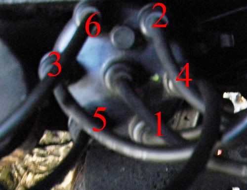
Quote: The Distributor Cap that is on the NEW Electronic Distributor has one of the Spark Plug Towers labeled as Number One.
True, but as a matter of mundane trivia, plug wire placement is entirely arbitrary so long as the 1-5-3-6-2-4 firing order is observed. The cam doesn't care where the rotor is physically pointed, so long as the rotor fires off the right cylinder at the right time. but you should probably just used the terminal labeled "1" for simplicity's sake.Quote: So when the Electronic Distributor is installed, the Rotor wants its Terminal's Right side at the Left side of the Number One Terminal in the Distributor Cap.
Sure, that will work.Quote: This can be done with some amount of precision because there is on hand a Distributor Cap with the top cut out of it, and it can be put on and with the Rotor pointing at Terminal Number One on the Cap, the Distributor can be turned so that the Rotor is where it should be as described above.
That will make it much easier to ballpark the timing.Quote: [10 BTDC is]quite a bit MORE than Lorrie is specified to have. Specifications on Lorrie's 225 Slant Six are Number One Piston fires at TDC. But Daniel says to advance it to five degrees BTDC.
Sure, 5 BTDC is good too.
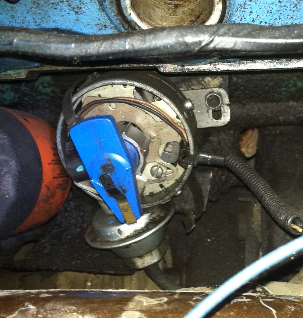
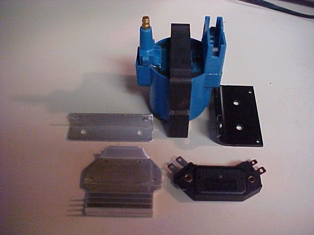
Quote: Have been looking at the Electronic Distributor and have noticed that the Reluctor has vertical Ridges on it, and that the in the middle of the Pick-Up Coil Assembly that there is a single Ridge on it. Would it be safe to assume that when one of the Reluctor Ridges passes the Pick-Up Coil Assembly Ridge that THAT is when the Coil fires off to the Distributor?
Yes, very safe. And you don't even have to trap me into a dentist chair for me to tell you it is safe. ![]() Quote: Am hoping to get an understanding of what all happens when the system functions.
The plugs fire!
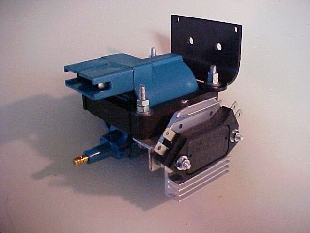
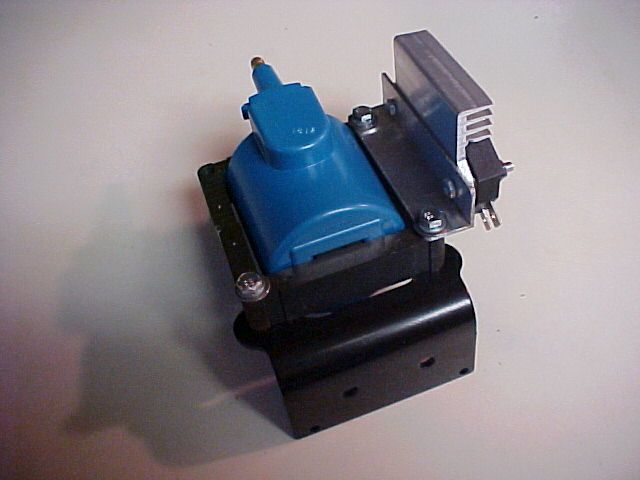
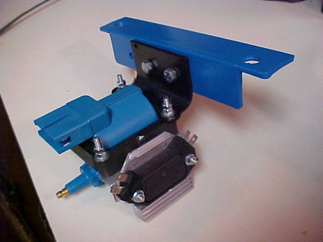
Quote: Anyway, at this point, just getting the Components arranged, assembled, and installed is the central focus.
And a great way to be. If it is worth doing, it is worth doing right. Go slow, be careful, do good quality work, and you will be fine.
|
Author: | JCAllison [ Thu Aug 02, 2012 3:05 am ] |
Post subject: | |
Quote: True, but as a matter of mundane trivia, plug wire placement is entirely arbitrary so long as the 1-5-3-6-2-4 firing order is observed. The cam doesn't care where the rotor is physically pointed, so long as the rotor fires off the right cylinder at the right time. but you should probably just used the terminal labeled "1" for simplicity's sake.
Hey Reed, In visualizing the Ignition System functioning, this very thought occurred to me. Didn't pursue the thought though because of thinking that there MUST be a reason for labeling a specific Spark Plug Tower as Number One. Quote: Sure, that will work.
It would make things easier, and lessen the anxiety.Quote: That will make it much easier to ballpark the timing.
Alright. Quote: Sure, 5 BTDC is good too.
Will just have to see how it goes. Quote: Yes, very safe. And you don't even have to trap me into a dentist chair for me to tell you it is safe.
Reed, this is beginning to look easier and easier. ![]() Quote: The plugs fire!
That, of course, is the result., but what was meant was that I wanted to understand HOW and WHEN, in the sequence of functioning that all of the Electronic Components do what they do.Quote: And a great way to be. If it is worth doing, it is worth doing right. Go slow, be careful, do good quality work, and you will be fine.
This whole project has been done in a "steady by jerk" mode. Lots of time spent contemplating the doing of any given task, while awaiting the acquisition of the materials and components. Then a concentrated physical effort to actually perform the assembly, installation, and adjusting of whatever was being done. Am hopefully at the end of the "Line of Dominoes" that has been dictating the sequence of all the stuff that has been gone into in order to get Lorrie up and running. Anyway, thanks for the VERY encouraging response. It has had the effect of increasing the confidence level here. Will keep you updated, and the JPGs will be along shortly. JC |
Author: | JCAllison [ Thu Aug 02, 2012 9:05 am ] |
Post subject: | |
Hey All, Thursday Morning Update: Got the Fin removed from the Control Module Heat Sink so that the Control Module's mounting holes matched the holes in the Heat Sink. This first JPG is of the STOCK Heat Sink: ![]() This JPG is of the Fin removed: ![]() Then what was left of the Fin had to be filed down: ![]() Then there are two registering Nubs on the Control Module that were they not removed would keep the Control Module from sitting flat on the Heat Sink. This JPG shows one of those Nubs. ![]() This next JPG shows that Nub removed: ![]() This JPG is of the Control Module mounted on the Heat Sink: ![]() This next JPG is of the Components un-assembled. Notice the Black Bracket on the right side of the JPG. THAT is the Bracket that came mis-boxed as a Control Module Heat Sink. It turned out to be the EXACT piece need to fasten the Component Assembly to the Angle Iron that will be bolted to Lorrie Floor at the Right Rear of Lorrie's mighty 225 Slant Six Engine: ![]() The next JPG is an upper view of the Components assembled. ![]() And this last JPG is of the under side of the Component Assembly. ![]() So the next thing that has to be done is to acquire the piece of Angle Iron. It will be cut and drilled to fit where it will go. Then the above Component Assembly will be fastened to it. Things are moving along here at a bewildering pace! ![]() Will keep you all updated on the progress. JC |
Author: | JCAllison [ Fri Aug 03, 2012 7:39 am ] |
Post subject: | |
Hey All, Friday Morning Update: Got the Bracket that bolts to Lorrie's Floor fabricated. And here's what it looks like: ![]() The left hole on the face that has three holes was already in the piece of Angle Iron. It isn't going to be used for anything. Got the first coat of Paint on it. Will give it a couple more coats before installing it. Things are moving along at a bewildering pace. JC |
Author: | JCAllison [ Fri Aug 03, 2012 11:59 am ] |
Post subject: | |
Hey All, Friday Afternoon Update: Have been doing the research to find Lorrie's Spark Plug Wires. Have MSD Brand 8.5mm Black Wires with Grey Boots on Ms. American. Would like to put the same look on Lorrie Van Haul. BUT, there are some glitches: The Stock Dodge Distributor Cap has 7mm Female Socket Style Connectors, thus the 8.5mm Wires wouldn't fit the Distributor Cap. Have looked EVERYWHERE for an HEI Male Spark Plug Style Distributor Cap for a 225 Slant Six. Alas, it appears that no one makes one. But in doing the research, THIS was found: MSD Ignition ASY10124 Power Tower Wire Adapter http://www.summitracing.com/search/Part ... on-Towers/ They fit into the 7mm Female Socket, turning the Distributor Cap into an HEI Style Connector. They are $4.99 each, which comes out to being $35.94 plus shipping. Have been having a hell of a time finding a set of MSD Black with Grey Boots Wires for a 225 Slant Six. Having the HEI Style Connector on both ends of the Wire would considerably lessen the search. Any comments? Would like to know what you all think because this item makes all the difference in what kind of Spark Plug Wires that Lorrie gets. Lorrie's Ignition Component Assembly Floor Mounting Bracket is finished. Twas given three coats of self etching primer, and then three coats of Ford Blue Engine Enamel, and the part is ready for installation. Am going to be cutting the Floor where the Bracket goes in order to be able to just loosen the Bolts and slip the Bracket out without having to completely remove the Nuts from the Bolts. This also permits the Bolts, Washers, and Nuts to be assembled on the Bench and then slipped into position to be tightened down. Also, there is no chance of the Floor Bracket coming loose because there are going to be two large Metal Screws holding the floor down and they will be screwed into the Floor Bracket. Anyway, am watching the weather-guessers prognostications about Ernesto, the Hurricane which is headed for the Gulf of Mexico. It's just East of Cancun. Am hoping that it continues West instead of turning North. Hope you all are well. JC |
Author: | walpolla [ Fri Aug 03, 2012 3:00 pm ] |
Post subject: | |
Hello, With all those bolt together connections, and painted components, do'nt forget that the control modules are extremely dependant on a good ground to operate. Better to address that point before fitting, and a possible fail to ground/function situation happening. Keep up the good work. regards,Rod ![]() |
Author: | Reed [ Fri Aug 03, 2012 3:20 pm ] |
Post subject: | |
Good point. I think running a ground strap from one of the HEI module's screws to the frame or the (-) battery terminal would do the trick. |
Author: | emsvitil [ Fri Aug 03, 2012 4:42 pm ] |
Post subject: | |
http://www.ebay.com/itm/MSD-ASY10124-Sp ... 2b&vxp=mtr It's still summit, but you may be paying less shipping...... |
Author: | JCAllison [ Sat Aug 04, 2012 2:53 am ] |
Post subject: | |
Hey All, Saturday Morning Update: Got the Control Module/Heat Sink/Ignition Coil Assembly fastened to the Floor Bracket. Here is how it came out looking: ![]() Am fabricating a Heat Shield that will be mounted on the Floor Bracket as a barrier between Lorrie's mighty 225 Slant Six Engine and the Control Module/Heat Sink. The Heat Shield will also have a 2" diameter Hose connected to route fresh, cool, dry air to flow over the Heat Sink Fins. Have to go to Livingston first thing this morning to run errands. Will keep you all updated. JC |
Page 5 of 12 | All times are UTC-08:00 |
Powered by phpBB® Forum Software © phpBB Limited https://www.phpbb.com/ |