Slant Six Forum
https://slantsix.org/forum/

Engine bay power distribution box install
https://slantsix.org/forum/viewtopic.php?t=45982
Page 1 of 2

Author:  Ross [ Tue Aug 16, 2011 5:27 pm ]
Post subject:  Engine bay power distribution box install

Well i finally got my engine bay fuse box installed. Its out of a 96 Dodge Caravan. Holds 9 bosch style relays, 3 smaller relays, 8 large fuses and 17 mini fuses. Currently I only have the starter relay and my driving lights hooked up. Next my hei relay and fuse will go in there then the headlights. It also has relays for the wipers so i might wire that up to my wipers.

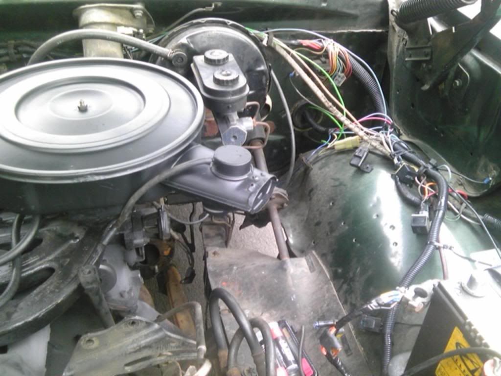
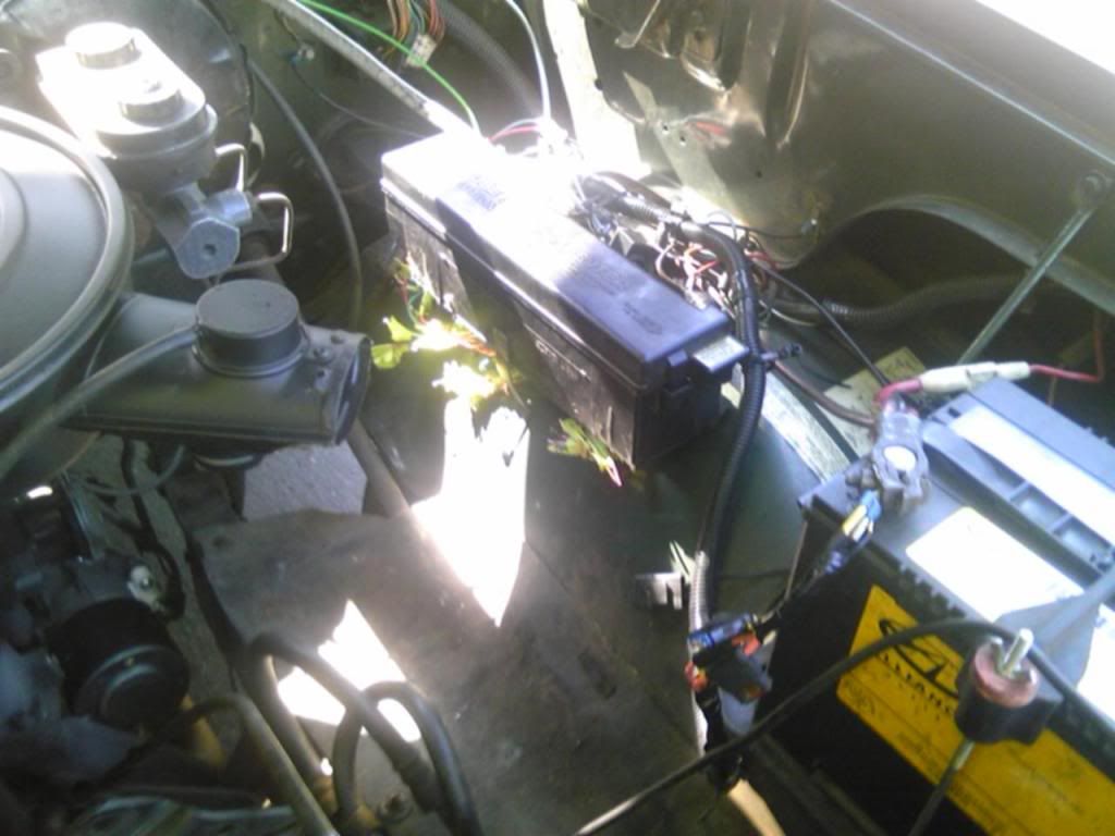
Here is the driver side before i installed the box. This is when i was putting a new starter in which is why there is no starter in there.
Image
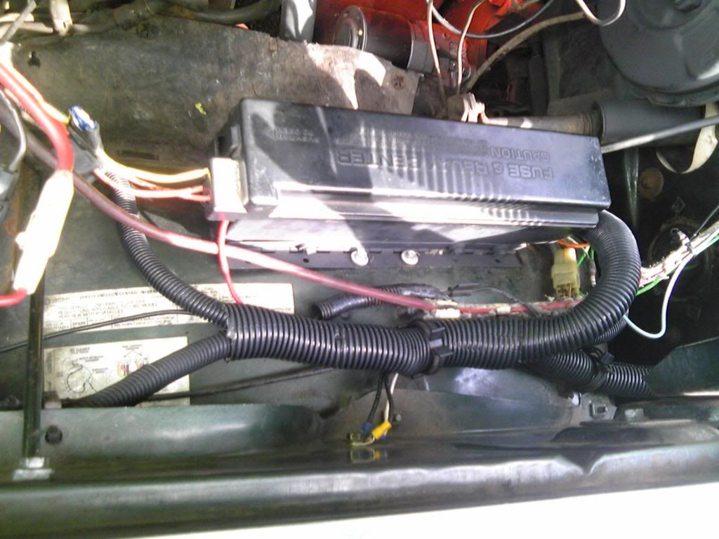
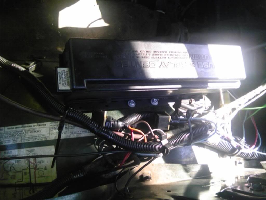
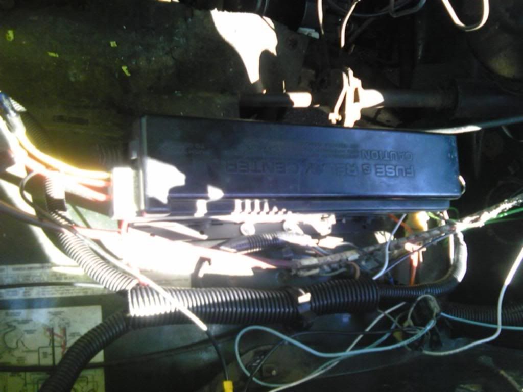
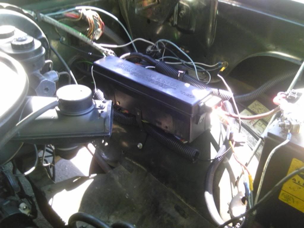
Here is the box installed and not wired up yet. I used one of the old brakets from the charcoal canister for the outside mount on the box and a long piano hinge so that i can flip it up to access the connectors.
Image
Image
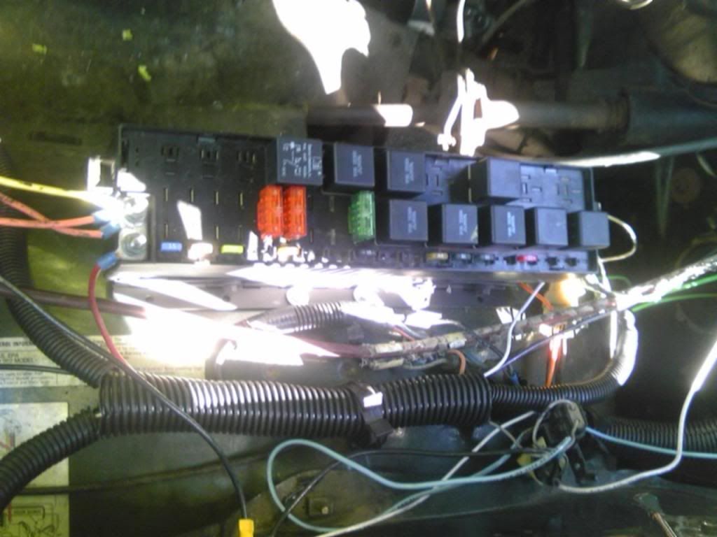
Here I have only the starter relay and fuse wired up. (The relay on the left and the orange fuse)
Image
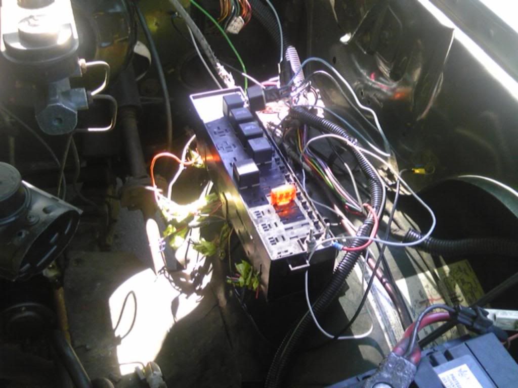
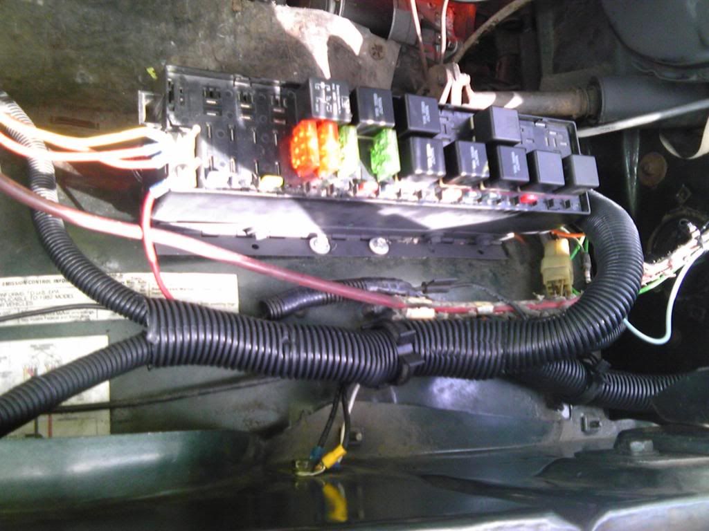
Here i have all of the relays and fuses that I had on me installed. Still some cleaning up of the wires to do.
Image
Image
Image

I used the positive wire that went to my starter relay from a welded splice which also has a fusible link in it for the main power to the fuse box.

Bosch style starter relay wire up:
Before I installed the fuse box I had replaced the old starter relay with a bosch style one. It was quite easy. On my truck there is a red wire which goes to the prong(s) on the old relay that says Batt. This wire will go to #30 on the bosch relay. There is a Brown wire that goes to the starter solenoid that goes to SOL on the old relay, this goes to #87 on the bosch relay. Green wire is ground, on manual transmissions like mine, this was grounded to the screw holding the relay on the fender, on automatic transmissions this goes to the neutral saftey switch, this wire goes to G on the old relay which will now go to #85 on the bosch. Then lastely we have the Orange wire which goes to I on the old relay, this goes to the ignition switch, this will go to #86 on the bosch relay. And there you have it, the change over to a bosch style starter relay that you can later wire in to a fuse box like mine if you wish.

Hope this helped anyone, inspired you to do something like this, or you just enjoyed reading my how to. I will update as i wire more things into this box and how well it works out for me.

Untill next time
Cody

Author:  Ross [ Wed Aug 24, 2011 10:39 pm ]
Post subject: 

Wired my ignition to the ABS pump relay and fuse in the power distribution center. Wired the main abs fuse to the extra switch on my dash so i can turn ignition on and off with out the key. Only problem is you could compression start it if you turn the switch on even without the key. But the steering wheel is still locked without the key.

Image
Image
Really cleaned up those wires there.

Author:  WagonsRcool [ Thu Aug 25, 2011 7:45 am ]
Post subject: 

As a mechanic, I really appreciate that detail on modern cars- a central fuse/junction box. It doesn't make up for all the other over- designed & under- engineered junk I see every day, but it IS nice.

Author:  Ross [ Thu Aug 25, 2011 10:00 am ]
Post subject: 

Yeah it is nice because I can store all of my fuses and relays and not have them pile up screwed into the fender or laying all over the place.

Cody

Author:  KenUSA [ Fri Sep 14, 2012 4:51 am ]
Post subject: 

Thanks for the inspiration. I picked one up and stripped out the factory bus bars. I am in the process of soldering in the circuits i need while keeping the circuit labels on the cover. ie. ignition, Horn, fuel pump, wipers,head and tail lights. I'll use a couple spares to wire my over drive.

The shape and size plus the solid main bus make this power center perfect for my project.
Thanks again.

Author:  mcnoople [ Fri Sep 14, 2012 3:51 pm ]
Post subject: 

If you have more pictures (close-ups and good quality) this would make a decent article for the main page. There are lots of people that are intimidated by a project like this and a step by step detailed guide might help them out. I am going with a bussman fuse/relay box, but your install looks real good. Nice work.

Author:  olafla [ Sat Sep 15, 2012 7:37 am ]
Post subject: 

Good choice, and good work, Cody.

Olaf

Author:  Sam Powell [ Sun Sep 23, 2012 7:09 pm ]
Post subject: 

Great job. That is an inspiration.

Sam

Author:  Dart270 [ Mon Sep 24, 2012 5:28 pm ]
Post subject: 

Yes, very cool indeed. Thanks to Ken also on the other thread.

Lou

Author:  Ross [ Thu Sep 27, 2012 8:30 pm ]
Post subject: 

Thanks for all of the comments everyone! Ive been busy lately which is why the delayed response. Unfortunately the pictures i have posted are the only ones i have. I had this box under my hood for quite soe time till i got tired of trying to tuck all of those little wires under the box when i added something. Plus the wiring harness i made for my headlights is 10ga and the wires on the box were i believe 20ga :shock: Needless to say my new setup has increased my light output a bit since the voltage isnt restricted anymore. Ill show some pics of my new setup.

.Image
Image

What i did with the new setup is a bought a Blue Seas systems12 fuse panel from amazon. I also bought a 5 pack of relays with connectors. I bought a 2 foot long 4ga cable to go to the fuse box (when i redo this i will be adding a 125amp fuse in there). I soldered and heat shrank every connection and was even able to get rid of some wires. The location of the box is temporary till i get my new battery cables installed and new marine type battery clamps (stud and wingnut style). I also want to make a new chassis and engine bay wiring harness as well as put relays on my blower motor to get the best performance out of my heater. I will post pictures when i do this but that wont be for awhile.

Author:  bbbbbb9 [ Fri Sep 28, 2012 6:16 am ]
Post subject: 

Ross, I hate to see all that work go to waste, but it does provide me with some validation. I'm rewiring my whole car and it's combining a 77 Aspen engine harness, a 64 Dart underdash harness, HEI and headlight upgrade. I wanted to put in slo blow Maxi fuses but chose to go the route of a box I had, some fuse holders and a terminal strip which I am currently combiming into a underhood electrical center so to speak. I saw Ken and your threads and began to get my usual, "There you go dummy, there was a better way" feeling.

Keep us updated.

thanks

Author:  Ross [ Fri Sep 28, 2012 8:48 am ]
Post subject: 

Well I saw the box sitting on my bench in the garage this morning and had the thought of tearing it apart and doing what Ken did and using the fuse box I have now as a new under dash fuse panel. I think itd do a much better job, or maybe behind the glove box, I have tons of room back there. although I was going to see if I can put an updated 2ND gen ram heater unit in my truck. wiring is very easy for me to understand so a task like redoing there fuse box or even making my own harness isn't very daunting I just need to get some label stud for my label maker so I can all the wires when I do so. You know how hard it is to differentiate 5 red 14GA wires all going to about the same location:shock:

Author:  mcnoople [ Sat Sep 29, 2012 3:23 pm ]
Post subject: 

http://www.cooperindustries.com/content ... _15300.pdf

This is the box I am installing in mine. It holds 10 fuses and 3 or 5 relays depending on relay used. There is also a 20 fuse 0 relay version of it available. The only real drawback is that you have to buy delphi metripak 280 pins for it and the special crimper for the pins is pricey. I have access to a gm factory crimper so it isn't a big deal for me. I figure $20 in pins and 2 boxes ($25 each) should supply me with almost all the fuse/relay capacity that I need.

For labeling wires I think I am going to use a simple numbered label set and apply clear heatshrink over the label to keep it clean, legible, and in place. If you want a cool free computer program to play around with there is one called "express pcb". It is a computer drafting program for wiring that is user friendly. I learned it without instructions in a couple of hours. With it you can make a wiring diagram of how you layed out your custom harness and then print it out (or save) for future reference. That way 5 years down the road you aren't left asking yourself "What did I do here?"

Author:  Dart270 [ Sun Sep 30, 2012 4:53 am ]
Post subject: 

I am confused as to why Ross went from the OEM minivan junction box to the Blue Seas one? Just curious.

That Cooper one also looks really nice, Mcnoople.

Lou

Author:  KenUSA [ Sun Sep 30, 2012 5:39 am ]
Post subject: 

The cooper panel is very nice looking, suitable for exposed, semi concealed install.
Mcnoople, those cad links are cool, maybe ill try one for Mac.

Page 1 of 2 All times are UTC-08:00
Powered by phpBB® Forum Software © phpBB Limited
https://www.phpbb.com/