Slant Six Forum https://slantsix.org/forum/ |
|
Engine Rebuild - Order of Steps https://slantsix.org/forum/viewtopic.php?t=51112 |
Page 1 of 3 |
Author: | Eatkinson [ Fri Feb 15, 2013 12:11 am ] |
Post subject: | Engine Rebuild - Order of Steps |
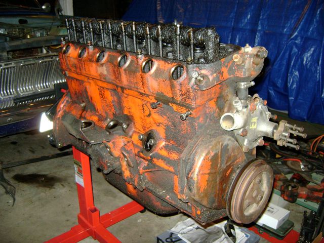
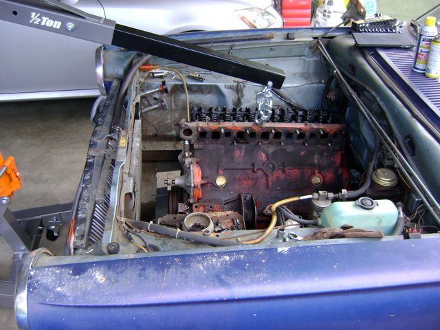
Last weekend, pulled the '63 225. Engine is currently on the stand, waiting for me to get to it. Was just looking at it tonight, and realizing I don't really know if there's a 'correct' order in which to continue dismantling. As of this point, I'd take the oil pump off, water pump, rocker assembly (leaving the valves as is for now), pull the damper off the crankshaft, remove the timing cover, etc., to get a second opinion. I could use some guidance as to, once the crankcase is open, what are next steps? I want to acid-wash the block or hot tank it, since the engine is filthy. But this seems like a last step, and only after you've removed everything from the engine (pumps, hoses, smaller things). Any advice would be welcome. |
Author: | slantsik [ Fri Feb 15, 2013 4:34 am ] |
Post subject: | |
A couple of things to do . Dont tip the engine up-side down without the head on,(or with the push rods removed) otherwise you will lose your lifters all over the floor!!! When pulling out the camshaft followers(lifters), mark them as you pull them out 1 by 1. (eg #1 IN ,#1 EX) You will need to do this if you intend to re -use the camshaft. Lifters wear into the cam lobes ,each having its own unique wear pattern. Also measure the piston to deck height , of the #1 and #6 cylinders.(at Top dead center). this will allow you to see if the block is decked parallel to the crankshaft centerline. It will also allow for some compression measurements,which will come in handy before machining. CC the head before pulling the valves out. Keep all individual cylinder parts together ie # 1 parts (piston ,rod ,valves, push rods ,springs,together ) The main reason is to help with any fault diagnosis, if you can identify what came from where, it can help put a story together about the engine,and any issues it may have. I like to clean parts as I pull them, rinse , dry ,and inspect, then put them into zip-lock bags with the name of the part printed in permanent marker. then they are ready to either paint prep or re install. Have a look through these http://www.slantsix.org/articles/articles.htm Have fun. Brendan. |
Author: | Red [ Fri Feb 15, 2013 7:59 am ] |
Post subject: | |
Hate to "jump ahead" and be a broken-record/PIA, but please take the extra time to upgrade to a double chamber brake master cylinder before putting the car back into regular service after your rebuild is complete. Some of us here have "learned the hard way" why this should be given high priority. Trust me: you WON'T be happy if you repeat our mistake and put this mod off til after the single MC has already failed (possibly resulting in unpleasant and/or expensive consequences). At speeds above 10 to 15 mph, stopping even a small A-body with nothing but the e-brake just doesn't cut it and that's all you'll have to get the job done if that single-pot MC takes a dump on you. |
Author: | DusterIdiot [ Fri Feb 15, 2013 8:53 am ] |
Post subject: | Some more procedures... |
Looks good... I usually do a once over an see if anything is visually a miss and jot it down on a note pad (bent puchrods, cracked rocker arm, etc...) Typically: 1) Remove all the accessories and brackets. 2) Drain the oil if you haven't yet, then remove the oil pan (this will allow you to then stick a drain pan under it and let gravity finish the job while working on the topside. 3) Check the geometry between the pushrod cups and the rockers, so you know if you do more than a clean up pass on the head you know if you need new pushrods. 4) Remove rocker assembly (keep bolts in place so the spacers and arms don't go sliding off the ends), 5) Remove pushrods. 6) remove the head-prepare for any last dashes of coolant to come out. Inspect the chambers, bores and piston tops for damage or signs of leanouts/carbon deposits/etc...also with a finger nail check the wear ridge at the top of the bore in each cylinder. 7) With magnetic probe or long nose pliers pull the lifters-if reusing them, save an egg carton out and label the lid 1-6 and which row is I and E, use some 'stuffing' (paper towel/shoprag/etc) to keep them in place. 8 ) Remove harmonic damper (insert 2x4 block between crank counter weight and pan rail for best stop). 9) Remove cam bolt, gear and timing chain (if you need leverage in getting the cam out, thread one of the head bolts into the cam for a longer handle... 10) If you are just going to rering/hand hone it/reuse the pistons, now is the time to use a ridge reamer on the top of the bore...if you are over boring, don't worry about it. 10) Make sure the drain pan is under the block and roll it upside down. 11) Go to work on getting the rear main seal removed (depending on year that's a 3/8" 6 sided socket or a 3/8" 12 sided socket...) 12) one at a time, remove the rod cap and set aside in the orientation that it will go back on the rod, using a long implement push the rod/piston assembly out of the block, if you are overboring and the rings are caught on the ridge get out the hammer and drive it out. Reassemble the rod cap and nuts, and proceed to the other 5 bores one at a time. 13) Remove the main caps and set aside so they can be reinstalled the same way they went in. 14) Remove crankshaft. 15) Reinstall main caps. 16) If you are documenting the old measurements now it the time to check bore wear, and bearing clearances. If you are getting new bearings, you will need to confirm your crank and cam journal sizes to order them, and confirm your overbore choice if going min. over bore...if going HP then no worries, it'll be more than anywear in the bores (60 over?) If they hot tank the block, it will not be good for the cam bearings, they will either be banking on new bearings, or if it's a good machine shop and this is on "the cheap" they can remove them and reuse them (I just plunk the money for new...) 17) get a large drainpan or lots of absorbables, and remove the block from the stand and set on the face (hopefully you tightened the mains, they make good handles for loading unloading the block). Good Luck and take your time, -D.Idiot |
Author: | wvenable [ Fri Feb 15, 2013 9:06 am ] |
Post subject: | |
Step number 1 - check wallet. Step number 2 - double check wallet. This is how I start any project! |
Author: | DusterIdiot [ Fri Feb 15, 2013 10:00 am ] |
Post subject: | Lol... |
Quote: Step number 1 - check wallet.
I figure that he already found the hole in the wallet and pocket by the machine shop...This is not something that can just be plugged using duct tape... Step number 2 - double check wallet. This is how I start any project! |
Author: | Doc [ Fri Feb 15, 2013 10:43 am ] |
Post subject: | |
Check to be sure all the rod caps have numbers stamped on the sides and that those number are clear and match... this helps to ensure that the correct rod cap stays with the same rod, in the correct oreantation. Vote # 2 for doing careful measurment on the deck heights of #1 & #6 bores. Write down these measurements. DD |
Author: | Eatkinson [ Sat Feb 16, 2013 11:16 pm ] |
Post subject: | Re: Some more procedures... |
Quote:
3) Check the geometry between the pushrod cups and the rockers, so you know if you do more than a clean up pass on the head you know if you need new pushrods...
What do you mean by this? "Check the geometry between them"? Please explain how to take the measurements. Thanks!
|
Author: | DusterIdiot [ Sat Feb 16, 2013 11:42 pm ] |
Post subject: | Eyeball method... |
Quote: "Check the geometry between them"?
This is a roll the crank over and look at the relation between the cup and the rocker arm, and especailly how many threads you ahve on the asjusting screw....once you start planing off the head or block (especialy a .100 cut), you may not have any more room for adjustment to use the stock pushrods and will be needing a set of custom length pushrods.-D.Idiot |
Author: | Eatkinson [ Sun Feb 17, 2013 11:55 am ] |
Post subject: | Re: Eyeball method... |
Quote: Quote: "Check the geometry between them"?
This is a roll the crank over and look at the relation between the cup and the rocker arm, and especailly how many threads you ahve on the asjusting screw....-D.Idiot I think understand your note about the possibility of needing new custom pushrods due to head or block planing creating less distance between the rocker assembly and cam. In this occasion, the stock pushrods would end up being too long to use, and I'd need a set of shorter custom pushrods, correct? |
Author: | olafla [ Sun Feb 17, 2013 8:56 pm ] |
Post subject: | |
Hi Eatkinson. Slantsik recommended the article section, I follow up and recommend that you also browse through the engine builds described in 'Best of Dr. Dodge' in the FAQ in the engine section. You'll find pics and comments there, that most likely will help you when dismantling the engine too. My advice: Take photos, take measurments, write your notes, mark every single litle part with what it is, and where it belongs. No matter how smart you are, don't trust your memory! Olaf |
Author: | DusterIdiot [ Sun Feb 17, 2013 9:24 pm ] |
Post subject: | Yes. |
Quote: Thanks, but what "relation" am I looking to understand? You said geometry - are you talking about some kind of angle or clearance between the cup and rocker arm? Do I need to slip a feeler gauge in there somehow to check a measurement? Please 'splain...
Basically you want to note if you have some room between the cup on the pushrod and the underside of the rocker arm, you should also note how many threads you have below the stamped rocker arm. Most likely you are going to need new shorter pushrods, but if you go that route and your rocker adjusters are not "in the middle" a problem may occur. This is not a calculation, it's just something to note before the build, so when you assemble you don't get caught in a "bind".I think understand your note about the possibility of needing new custom pushrods due to head or block planing creating less distance between the rocker assembly and cam. In this occasion, the stock pushrods would end up being too long to use, and I'd need a set of shorter custom pushrods, correct? -D.Idiot |
Author: | Eatkinson [ Sat Feb 23, 2013 11:13 am ] |
Post subject: | Re: Some more procedures... |
Quote: Looks good...
When you say this, do you include the oil pump in this group?Typically: 1) Remove all the accessories and brackets.... -D.Idiot I ask because I'm having a challenge removing the pump and body. The impeller doesn't want to pull out, but I can't see how it would, and certainly not the pump drive gear from inside the crankcase. Is there a trick to removing, or do I not need to worry about it at this stage of my game? I have to remove the rocker arm assembly, pushrods and head today. |
Author: | Fopar [ Sat Feb 23, 2013 2:07 pm ] |
Post subject: | |
There is either 5 or 6 bolts that hold the pump on the block (yes there are 2 types of pumps). Look to see you have taken all the bolts out. Richard |
Author: | DusterIdiot [ Sat Feb 23, 2013 3:40 pm ] |
Post subject: | Oil pump... |
Just as Fopar says you have 5-6 bolts to take out (need a thin wall 1/2" socket for 2-3 of them due to location). You should not take the cover plate off the pump. If the engine has been around a while, the gasket may get petrified...I usually take a small rubber hammer and tap on the filter flange to get it loose once it moves you can pull the pump out of the block. This will be only necessary if removing the camshaft for a rebuild. -D.Idiot |
Page 1 of 3 | All times are UTC-08:00 |
Powered by phpBB® Forum Software © phpBB Limited https://www.phpbb.com/ |