Slant Six Forum https://slantsix.org/forum/ |
|
No spark on the HEI - help! https://slantsix.org/forum/viewtopic.php?t=54185 |
Page 1 of 1 |
Author: | Eatkinson [ Mon Dec 30, 2013 2:48 pm ] |
Post subject: | No spark on the HEI - help! |
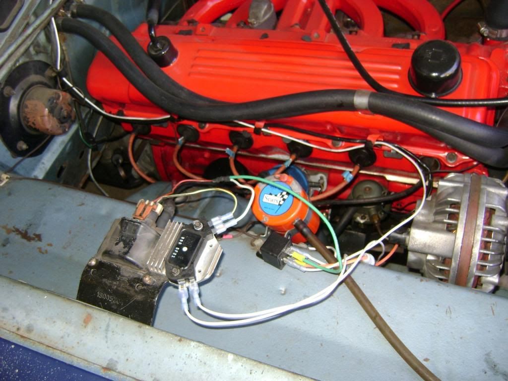
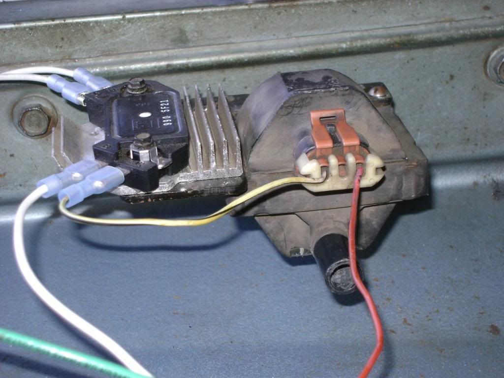
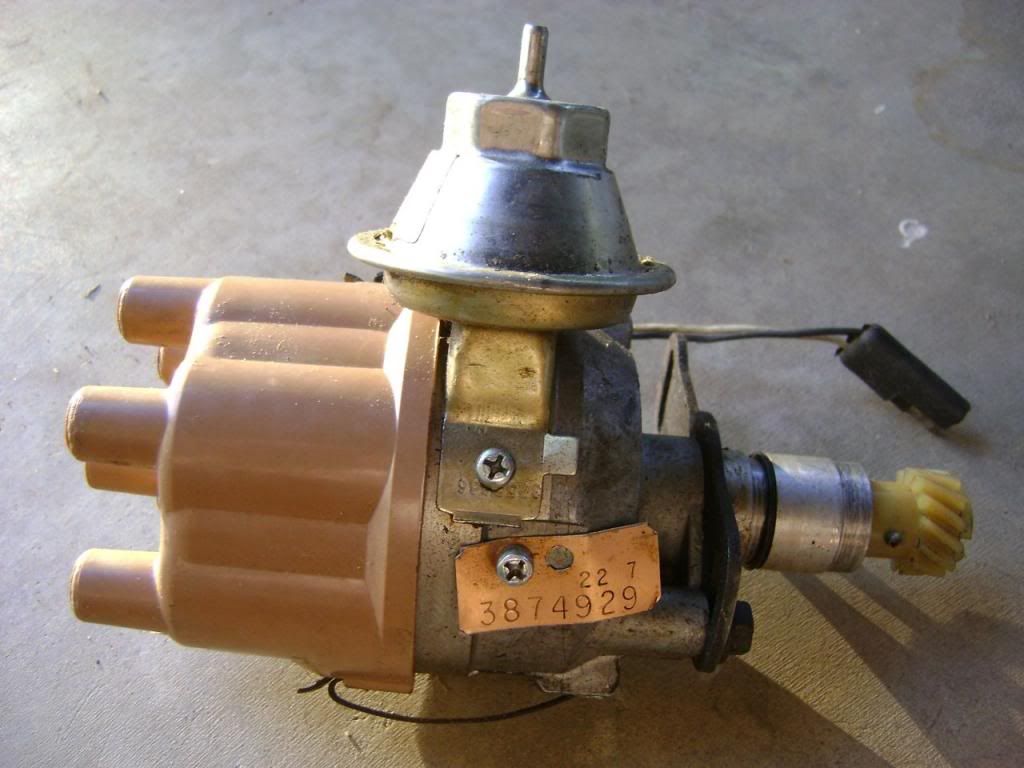
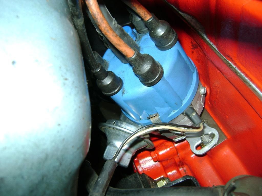
Converting from points to HEI. Did the equipment installation this weekend with help from some of you in a different thread, thanks. ![]() Update: I have no spark at all. Attempting to diagnose. Here's some things I did in the installation that may or may not affect whether I have spark: 1. Installed an original, previously-used GM HEI setup (bracket, heat sink, e-core coil, module) purchased from a parts yard. Swapped the module for a new module that gives the correct needed waveform. I assume I have the positive and negative coil terminals designated correctly since the coil is NOT marked at all. Oval connector on the top has three pins inside. I assumed orange wire/pin was positive, the white/black striped wire/pin was negative. There's a center pin in the connector that should be for a tach. Not used. ![]() Question A: How do I test the original e-core coil to determine it's good? Question B: Should the orange wire/pin be positive, and the white/black wire be negative? Question C: If you try to measure the resistance rating on the coil-to-cap cable, what is a good/acceptable reading on my multimeter, measuring ohms? I'm using the original cable supplied with the setup, between the coil output and the distributor cap. It's a male-male cable. I am trying to determine it's condition and if this could be contributing to my problem. If I'm reading the multimeter right, it's resistance rating is measuring about 700 ohms right now. 2. When I swapped the original GM module for a new module with the correct waveform, I wiped dielectric grease over the bottom of the new module before attaching it to the heatsink. Assume this is correct. 3. I purchased a "rebuilt" 1977-1980 super six PN:3874876. Here is my original thread I posted after buying and receiving two incorrect distributors. To be honest, I don't know how to tell if the correct super six distributor I bought has actually been rebuilt. It seems dirty inside, and it's covered by some kind of silver paint outside. I was preparing to install the distributor last night, and I noticed the drive gear was chipped. Rebuilt? I think not.... I swapped the drive gear from one of the wrong distributors and installed the super six dizzy. Question A: How do I know the correct distributor has actually been rebuilt? Question B: How can I test that the components inside the distributor are functioning as required? Question C: I've read a couple posts that state if you replace the distributor drive gear, that new gears sold have the roll pin hole drilled in the wrong location. I took the drive gear off of the incorrect distributor (below) and installed that. I wonder though if it is a used gear or a new gear? It looks like it has had minimal wear and has never been exposed to oil. What would a hole drilled in the wrong location do? Look at the picture and tell me if this gear could be causing a problem with getting spark. I wouldn't think so. I'm wondering if simply removing and installing it on my super six dizzy would cause other problems.... ![]() 4. I tapped #30 on the relay to the Alternator B+ (the "Output" terminal, that post that sticks out from the back). That is correct, yes? ![]() 5. I tried swapping the module right-side connections that connect to the distributor leads in an effort to get it started. The engine just cranked and it had no effect at all. 6. I already have a Standard Bluestreak CH-410X dizzy cap and the Echlin MO-3000 rotor. Installed these on the super six dizzy. They should be fine. ![]() Can anyone guide me as to why I'd have no spark at all? I have double and triple checked my wiring against the instructions on Slant Six Dan's original HEI conversion post. Thoughts welcomed! I need to get the Dart back running asap. Don't want to have to swap back to points if I don't have to. |
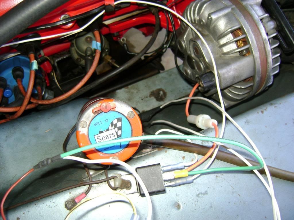
Author: | Eatkinson [ Mon Dec 30, 2013 3:37 pm ] |
Post subject: | |
One update. Measured the HEI coil with my multimeter for ohms across positive and negative terminals and got about a 1.6 ohms reading. Don't know what's specified for this coil - forget which model & year Chevy it came out of. |
Author: | oldskoolracer [ Mon Dec 30, 2013 3:58 pm ] |
Post subject: | |
Where are you pulling your ignition switch signal from...? Have you checked for power while cranking at the relay? You may be on the wrong circuit... Yes pin #30 is right for power in, it may be better to pull from the batt and not the terminal off the alternator. The battery acts like a voltage stabilizer and will reduce voltage spikes through the module and make sure it is fused... I dont see one in your pics... Pin #87 should be going to your coil/module b+ terminal. pin #86 should be your switched source, and pin #85 should be grounded... (these two will work if reversed too) Find the wire that is hot while cranking it and hook it to the (+) on the coil or module, then use the wire that is hot in the "on" position and use it to trigger the relay... This will give you the momentary 12v while cranking through the original wiring, then the relay will take over and supply battery voltage while the engine is running... 1.6ohms on the primary side of the coil should be fine, if it were way high Id be worried or no reading at all means its shorted "open"... |
Author: | Eatkinson [ Mon Dec 30, 2013 6:01 pm ] |
Post subject: | |
Quote: Where are you pulling your ignition switch signal from...? Have you checked for power while cranking at the relay? You may be on the wrong circuit...
Where the connectors used to mate to the ballast. Connected the push-on connectors together via a short line and two spade connectors, then spliced from the middle of that line. Quote: Yes pin #30 is right for power in, it may be better to pull from the batt and not the terminal off the alternator. The battery acts like a voltage stabilizer and will reduce voltage spikes through the module and make sure it is fused... I dont see one in your pics...
It's the fourth picture down. You can see the orange wire with the in-line fuse connector running from the Output of the alternator into the relay - going to #30.Quote: Pin #87 should be going to your coil/module b+ terminal.
'Tis. There's a single orange wire from the coil+. Soldered together end of that line and the two leads: one to Module B, and one to #87.Quote: pin #86 should be your switched source
That's spliced from the ballast.Quote: pin #85 should be grounded... (these two will work if reversed too)
Yep, 'tis.Quote: Find the wire that is hot while cranking it and hook it to the (+) on the coil or module, then use the wire that is hot in the "on" position and use it to trigger the relay... This will give you the momentary 12v while cranking through the original wiring, then the relay will take over and supply battery voltage while the engine is running...
Hmmm..... ![]() Quote: 1.6ohms on the primary side of the coil should be fine, if it were way high Id be worried or no reading at all means its shorted "open"...
Glad to know that.So...you're thinking it's a combination of line voltage from the alternator, and that it's not getting switched on at the ignition, nor triggering? Hmmm! Wonder why with my connections it wouldn't already be doing that?? |
Author: | nuttyprof [ Mon Dec 30, 2013 6:23 pm ] |
Post subject: | |
The 2 dk blue wires are run, the dk blue/brown wires are start ( the dk blue of the dk blue/brown pair went to the coil). If you connect all 4 wires together at the ballast and use the blue wire that used to go yo the coil you should have both start and run. For testing you could set up a 12v lightbulb with leads so you can wedge the wires into the terminals you want to test, if the light glows you have power! If I were you I'd test in this order, power to run/start wire, power at #86, power to #30 at relay (possibly fuse bad ?), power at #87, ground good at #85. If all that checks out ok then you have a bad module, coil, or pickup in dist. |
Author: | Charrlie_S [ Tue Dec 31, 2013 4:53 am ] |
Post subject: | |
Take one of your old electronic distributers. Check the gap between the reluctor, and the pickup coil (set at about ..006-008). Remove the plug from the distributer in the engine, and connect to the old distributer. Turn the ign on, and spin the distributor, by hand, and see if you have spark. If you do, the problem is in the new distributor (pickup gap too large, bad pickup coil, or dist not turning). PS: Have the coil spark wire near ground, but not touching. (you want a spark gap). |
Author: | Danarchy [ Tue Dec 31, 2013 8:07 pm ] |
Post subject: | |
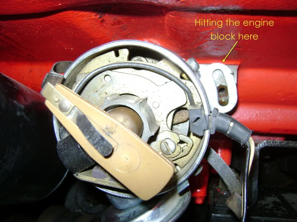
![]() so the bolt on the bottom of the distributor is Max'd out all the way the other direction? ![]() |
Author: | Eatkinson [ Tue Dec 31, 2013 10:17 pm ] |
Post subject: | |
Quote: so the bolt on the bottom of the distributor is Max'd out all the way the other direction?
It was.
![]() |
Author: | Danarchy [ Wed Jan 01, 2014 11:39 am ] |
Post subject: | |
![]() |
Author: | 64ragtop [ Wed Jan 15, 2014 11:14 pm ] |
Post subject: | |
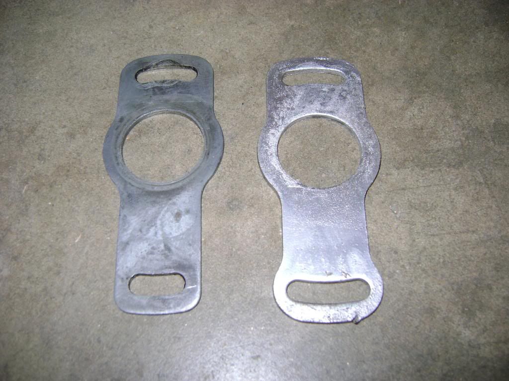
I would bet that the plate with the hump is from a lean burn dizzy, and was designed to do exactly what it's doing - limiting the possible timing adjustment. BC |
Page 1 of 1 | All times are UTC-08:00 |
Powered by phpBB® Forum Software © phpBB Limited https://www.phpbb.com/ |