Slant Six Forum
https://slantsix.org/forum/

HEI conversion question
https://slantsix.org/forum/viewtopic.php?t=59018
Page 1 of 2

Author:  bashmaki [ Sun Jan 24, 2016 10:23 am ]
Post subject:  HEI conversion question

I'm having some trouble with this conversion blowing HEI modules. I've gone over all the materials here and I've discovered some of the problem, I believe. One question I can't seem to find any info on is the particular coil I'm using. I have the pig tail and plug in module from the donar vehicle (1996 Jimmy). The color code is where I'm lost.

Pink= power
So then I have a white wire and a white with black stripe. Which one of those is used to go to the module and which one is the tach. wire.

Thanks guys

Author:  Reed [ Sun Jan 24, 2016 10:57 am ]
Post subject: 

Pay no attention to the color of the insulation on the wire. You need to look at what each terminal on the HEI module is supposed to connect to.

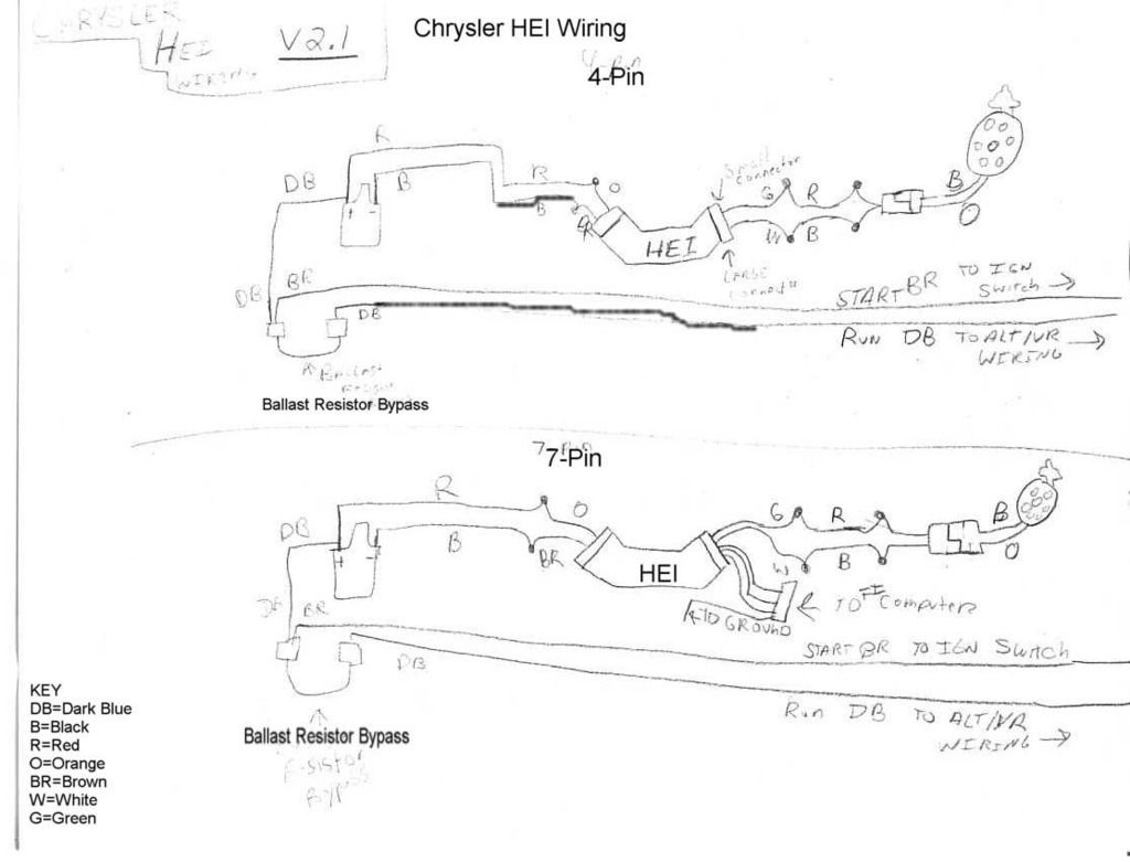
Here are a couple simplified HEI ignition wiring diagrams that leave out the relay for clarity:
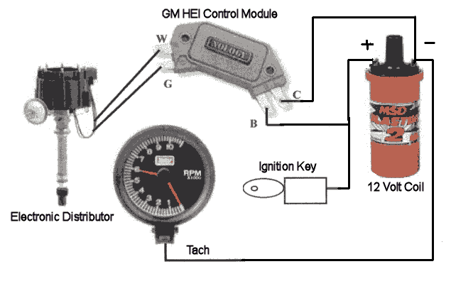
Image

Image

The 7 pin wiring diagram is for if you were using a GM batch fire fuel injection system and need the signal from the HEI unit to trigger the injectors. Ignore it.

Author:  Pierre [ Sun Jan 24, 2016 11:42 am ]
Post subject: 

A 3 wire ignition coil? You got a coil meant for computerized ignitions. Those types of coils have built in coil drivers. Fancy way of saying part of the HEI module is already built in the coil. You need a 2 wire coil.

Author:  coconuteater64 [ Sun Jan 24, 2016 11:46 am ]
Post subject: 

Did you use the heat transfer paste? Them cook pretty fast if they get hot.

Author:  bashmaki [ Sun Jan 24, 2016 5:44 pm ]
Post subject: 

I apologize for getting this under the wrong topic; thanks for moving it.

First off : this coil does not have anything labeled on it; no letters to signify anything so its a guessing game. There is just the weather proof plug with three wires coming out of it.I used the white one with the black stripe this time along with the pink one. I am assuming the white one is the tach wire. Truck is running fine now other than some idling issues that are probably carb. related.

I read many different articles on doing this conversion and some of them eliminated the relay. This is the way I did mine and I can't help but think that was a major part of the problem with blowing modules. I mean I cleaned everything with soap and water and then greased the module and even greased the heat sink where it screws to the stock GM mount. Although I had a good ground through the GM mount I ran a strap to ground after blowing the first module.

I now have a relay properly situated into the circuit and hopefully that will take care of the module blowing problem. I blew 3 modules total. The first was an elcheapo off of eBay with the same number as the Echlin module. Thought I had the right one and probably did; just not the right brand.
The second and third modules were both Standard brand modules.

After blowing these two I ended up hooking up the lean burn system again so I could get to town (30 miles) after another module. Both of our other vehicles were gone.

I now have it up and running on the Echlin module with a relay in place as well.

Thanks for the tips all.

Author:  Reed [ Sun Jan 24, 2016 6:02 pm ]
Post subject: 

I did some diggging on the internet and found this for you:

Circuit labeled A -Pink Wire:
Power (12 V) Circuit.

Circuit labeled B -White Wire:
Tach Signal for the tachometer in the instrument cluster if equipped.

Circuit labeled C -White with Black stripe Wire:
Switching Signal Circuit. This wire (circuit) comes from the ignition module.

From this page:

http://easyautodiagnostics.com/gm/4.3L- ... -the-icm-1

Author:  bashmaki [ Sun Jan 24, 2016 7:46 pm ]
Post subject: 

Quote:
I did some diggging on the internet and found this for you:

Circuit labeled A -Pink Wire:
Power (12 V) Circuit.

Circuit labeled B -White Wire:
Tach Signal for the tachometer in the instrument cluster if equipped.

Circuit labeled C -White with Black stripe Wire:
Switching Signal Circuit. This wire (circuit) comes from the ignition module.

From this page:

http://easyautodiagnostics.com/gm/4.3L- ... -the-icm-1
Ok Reed thanks for the verification. I looked at the link and that is the exact coil/ module & bracket I started with and, this time, that is the way I wired it.

Author:  bashmaki [ Sun Jan 24, 2016 7:48 pm ]
Post subject: 

Quote:
I did some diggging on the internet and found this for you:

Circuit labeled A -Pink Wire:
Power (12 V) Circuit.

Circuit labeled B -White Wire:
Tach Signal for the tachometer in the instrument cluster if equipped.

Circuit labeled C -White with Black stripe Wire:
Switching Signal Circuit. This wire (circuit) comes from the ignition module.

From this page:

http://easyautodiagnostics.com/gm/4.3L- ... -the-icm-1
Ok Reed thanks for the verification. I looked at the link and that is the exact coil/ module & bracket I started with and, this time, that is the way I wired it.

Author:  Pierre [ Mon Jan 25, 2016 1:04 am ]
Post subject: 

Another wire just for a tach? Hmm, why would they do that instead of just saving a penny and put two wires on one terminal? Normally coil - is the tach line also. Unless those two terminals aren't tied together and the tach is an inductive pickup type.

I guess I'll revise my statement - modern 3 terminal coils include the driver built in.

Author:  DadTruck [ Mon Jan 25, 2016 4:32 pm ]
Post subject: 

typically there is a lot of good info on this forum, in this case, folks seem to be adding complexity,,

1) pink, switched power supply, could be coil +

2) white, tach wire

3) white and black stripe, coil negative


I use this same coil - GM module on the 83 D150 with good results and for now on the 68 Cuda,

good choice :)

Author:  bashmaki [ Tue Jan 26, 2016 10:18 am ]
Post subject: 

Dadtruck, thanks. I need a bit of reassurance after blowing 3 modules. But I think that is behind me . . .hopefully😌.

Reed, I book marked that reference page you linked above. That site should prove to be an invaluable site in the future, thanks again. I'd recommend it to anyone that messing with numerous types of vehicles.

Author:  Charrlie_S [ Sat Jan 30, 2016 2:52 am ]
Post subject: 

Actually the white wire and the white wire with black stripe are electrically the same. I was pretty sure that was the case, when the question was first posted, but I couldn't find the diagram to prove it. GTS225 just posted the diagram in another thread. http://lt1swap.com/1996_vortec_5.7/cmp_ ... il_5.7.gif

Author:  Reed [ Sat Jan 30, 2016 9:42 am ]
Post subject: 

Quote:
Actually the white wire and the white wire with black stripe are electrically the same. I was pretty sure that was the case, when the question was first posted, but I couldn't find the diagram to prove it. GTS225 just posted the diagram in another thread. http://lt1swap.com/1996_vortec_5.7/cmp_ ... il_5.7.gif
This is true. Ford e-core coils are wired the same way, but the wire colors are different. There are separate tach and coil - wire, but they both go to the coil - terminal.

Author:  Pierre [ Sat Jan 30, 2016 11:56 am ]
Post subject: 

Just trying to analyze the failure modes. If he got the coil polarity reversed that wouldn't do anything to the module. If he used black & black/white and left the pink out that would certainly cook the module then as if they were both electrically at same point it would effectively short the module out.

Author:  bashmaki [ Sat Jan 30, 2016 3:03 pm ]
Post subject: 

Quote:
Just trying to analyze the failure modes. If he got the coil polarity reversed that wouldn't do anything to the module. If he used black & black/white and left the pink out that would certainly cook the module then as if they were both electrically at same point it would effectively short the module out.
I did not do what you are suggesting here. In every application I had the pink wire for the + side.
What I failed to do was wire in a relay ; as stated above in this thread.

In every event the truck ran before the module failure. In every event the wiring was the same way except for how it is now. Now there is a relay in place. I think the wiring of a relay into the system is essential to the longevity of the module.

My theory that either the white or white/black are essentially the same must be true. I didn't know this for a fact because I had no idea how that modular plug was wired to the coil. When you think about it tho; the tach is always wired to the off (-)side of a standard coil. Knowing this would tell us that on this modular tail if one wire is for the tach and the other the off side or (-) side; they must both be essentially the same. I suppose I could have verified this with an ohm meter.

Page 1 of 2 All times are UTC-08:00
Powered by phpBB® Forum Software © phpBB Limited
https://www.phpbb.com/